Setting up for EEG
This page explains the most basic setup for processing EEG data using your OpenBCI board and gold cup electrodes.
Related Headware
To learn more about specific OpenBCI headwear and how to set them up for EEG, follow the links below.
What You Will Need
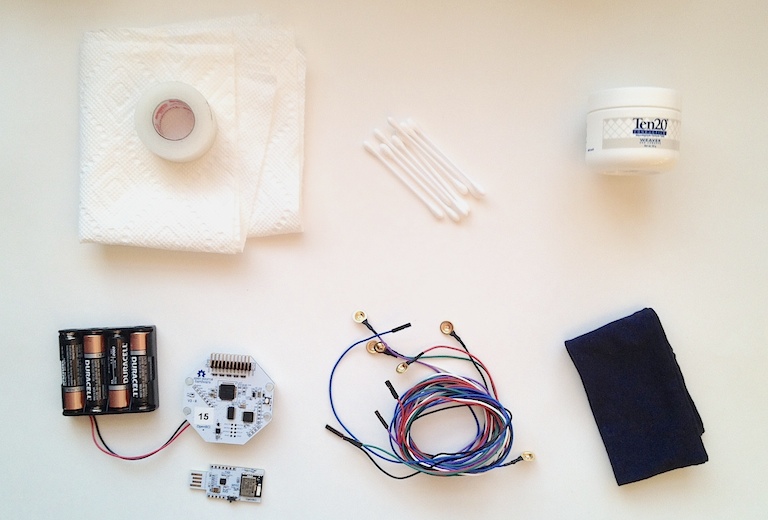
Necessary:
- Ten20 conductive electrode paste (or other conductive electrode gel)
- Cyton board, USB Dongle, and battery pack OR Ganglion Board
- x4 AA batteries
- x6 gold cup electrodes
Before applying Ten20 paste on subjects with long hair, part the hair at 10-20 international standard electrode positions.
If you are using an OpenBCI electrode starter kit, use the following electrodes to be consistent with the GUI's color-coding protocol:
- Black
- White
- Purple
- Green
- Blue
- Red
Optional:
- Paper towels for cleaning excess Ten20 paste
- Medical tape (or other tape) for adding extra stability to electrodes
- Ear swabs for cleaning paste from electrodes, once you're finished
1. Connect your electrodes to OpenBCI
Connect the electrode wires to your Cyton board as shown below. The proper wire connections are shown in the table as well. In the image below, you can see pins N1P through N8P on the Cyton. These correspond to the 8 channels available for data.
On the Ganglion, you have pins 1 through 4, corresponding to the Ganglion's 4 channels available for data. Please note, the four switches on the Ganglion should be set to 'DOWN' for EEG. Explanation in detail here.
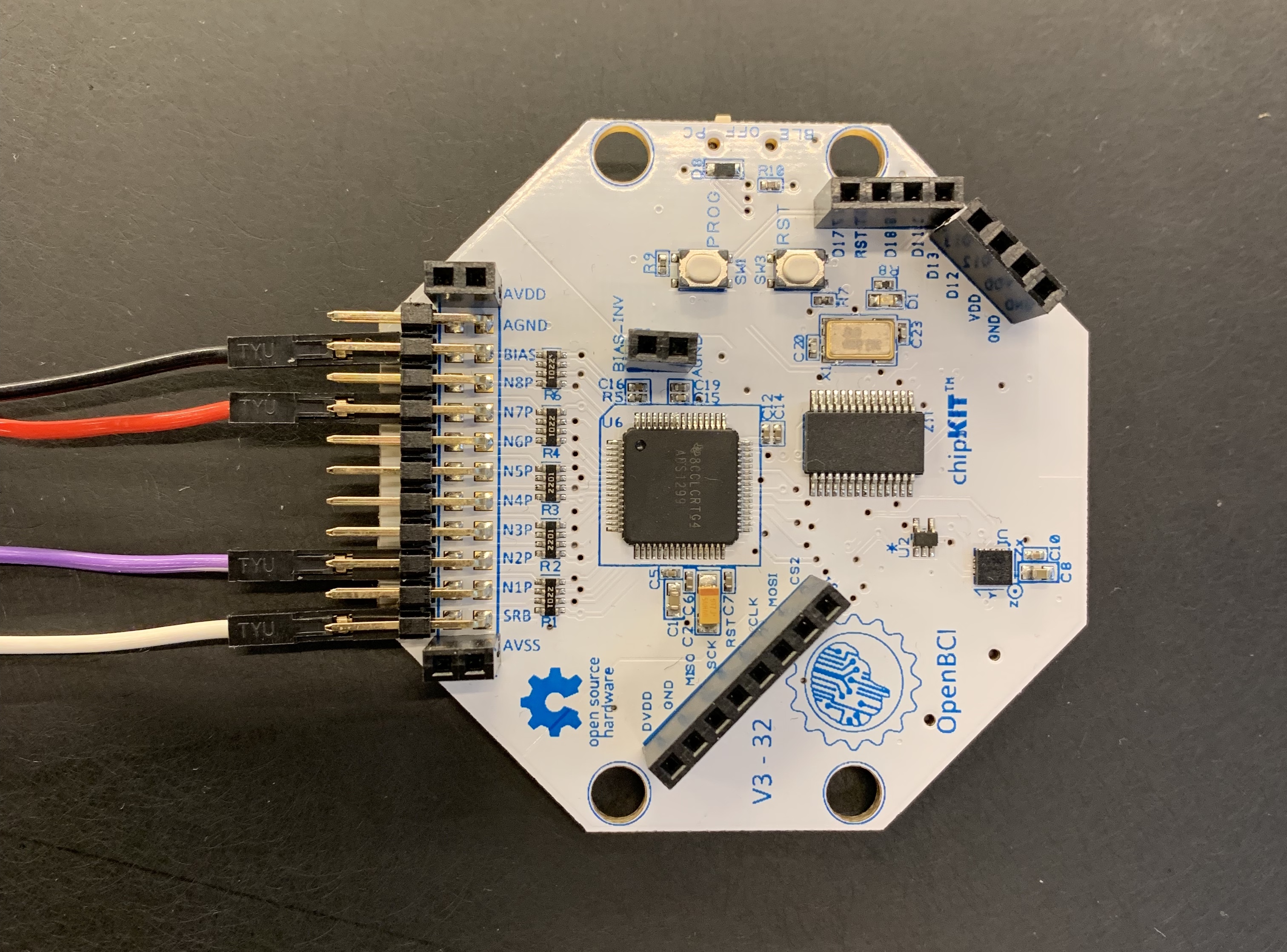
| Electrode Wire Color | Cyton Board Pin | Ganglion Board Pin | Function |
|---|---|---|---|
| white | SRB2 (bottom SRB pin) | REF (top pin) | Reference Pin |
| black | bottom BIAS pin | D_G (top pin) | Noise-cancelling Pin |
| purple | 2N (bottom N2P pin) | +2 (on top row) | Analog input |
| red | 7N (bottom N7P pin) | +4 (on top row) | Analog input |
The white and black electrodes must always connect to the SRB2 pin and the bottom BIAS pin, but the purple and red electrodes can be connected to any of the N1P through N8P channels (or pins 1 through 4 in the case of the Ganglion). We decided to use channels 2 and 7 for this tutorial. The results with Ganglion should be the same, but signals will show up on channels 2 and 4.
2. Connect your electrodes to your head and body
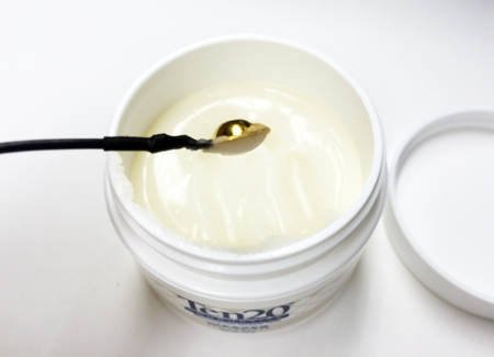
a) We're going to start with the electrodes on your head. Begin by scooping Ten20 electrode paste into your white gold cup electrode. This is going to be your reference (or SRB2) electrode for the other electrodes on your head. Fill the electrode so there is a little extra electrode paste spilling over the top of the gold cup, as seen in the picture to the right.
Note: Use a paper towel or napkin to remove excess electrode paste as you are applying your electrodes.
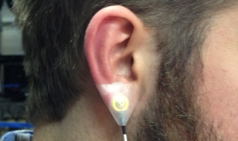
b) Now apply this electrode to either one of your earlobes (either A1 or A2 as seen on the 10-20 system image below). You can use some medical tape (or electric tape!) to give this electrode some extra stability, ensuring that it does not fall off. This electrode is the reference that all of the EEG electrodes on your head will be measured in comparison to. The uV reading that will appear in the GUI's EEG DATA montage is a measure of the potential difference between each electrode and this reference electrode (SRB2). Check out the other docs on how to maximize the usage of the other pins!
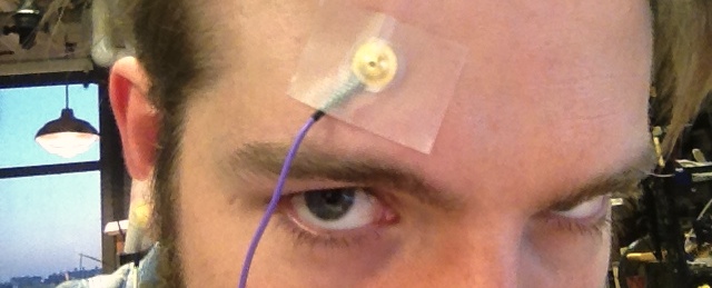
c) Follow the same procedure for the purple electrode and apply it to your forehead 1 inch above your left eyebrow (as if you were looking at yourself) and an inch to the left of your forehead's centerline.
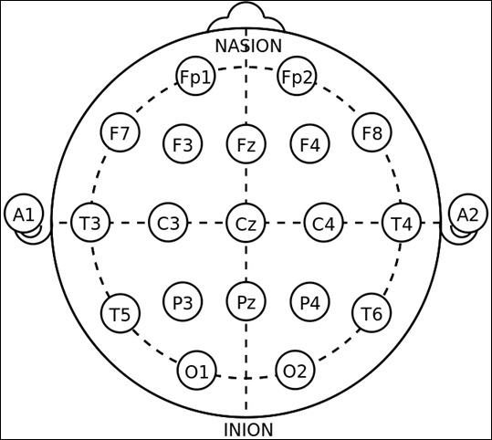
This electrode location is Fp2 on the 10-20 System. The 10-20 System international standard for electrode placement in the context of EEG. Fp indicates the a "frontal polar" site.
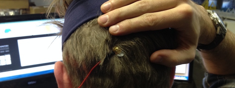
d) Now follow the same procedure for the red electrode and place it on the back of your head, 1 inch above the inion (as seen on the 10-20 system), and 1 inch to the left. This electrode location is O1 on the 10-20 system. The 'O' stands for occiptal, meaning above your occipital lobe (or visual cortex).
Note: to do this, pull your hair aside and make sure the electrode is nested as deeply as possible, with the electrode paste making a definitive conductive connection between your scalp and the gold cup.

e) Now follow the same procedure as step 2 above to apply the black electrode to your other earlobe (either A1 or A2 from the 10-20 system). The black electrode is connected to the BIAS pin, which is used for noise cancelling. It is similar to a GROUND pin, which establishes a common ground between the Cyton board and your body, but it has some extra destructive interference noise cancelling techniques built in!
You're now done connecting electrodes to your noggin! I like to use a cheap cotton hairband to add extra stability to all of the electrodes connected to my head, by placing it gently on top of all of the electrodes.
Due to the fact that the electrodes collecting EEG data are connected to the Negative inputs of the ADS1299 and the common reference is connected to the Positive Input through SRB2, the saved raw data from the OpenBCI GUI will appear inverted when processed in another application.
If you would like to reverse this polarity, it is recommended to do so through software and not change the hardware setup of OpenBCI. This is because SRB2 offers much more flexibility as compared to SRB1 when used as a common reference connection. To reverse the polarity of the data through software, you will have to pass the raw data through a band pass filter between 0.5Hz and 45Hz (to remove the DC offset) and then multiply by -1.
3. Launch the GUI and adjust your channel settings
a) If your OpenBCI GUI is not already running, relaunch it and configure the DATA SOURCE mode to LIVE (from Cyton) and Serial (from Dongle). Select your Cyton board from the list of devices, set the Channel Count to 8, and click START SYSTEM. Refer to section IV of this guide for more information on this process.
If you're using the Daisy Cyton board, still set the Channel Count to 8, even though the Daisy has 16 channels. Nothing will go wrong if you start the system with 16 channels, except the Time Series display will be unnecessarily cluttered.
b) Click START DATA STREAM to begin streaming data from your board. You should see live data from your body (and the unattached channels) streaming into the Time Series montage on the left side of the GUI.
c) Now we are going to power down the channels we aren't using. Do this by clicking the circular channel number buttons outside of the left side of the Time Series montage. Each time you power down a channel, the channel will show a burst of signal and then settle at 0 mV.
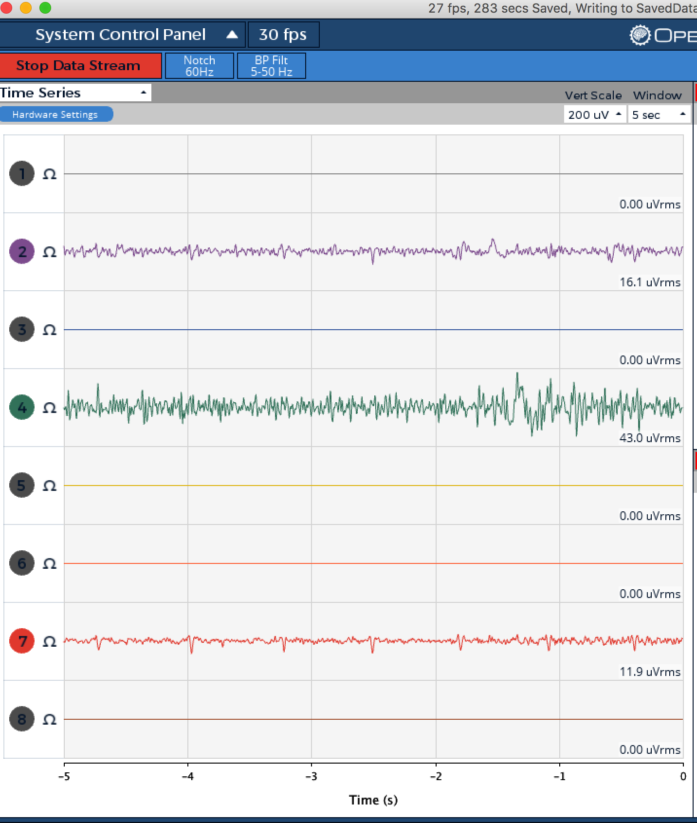
We are only using channels 2 and 7, so power down every other channel. You can also power down the channels with keyboard shortcuts (1-8). Power them back up with [SHIFT] + 1-8. If you are working with a daisy module, channels 9-16 can be powered down with q, w, e, r, t, y, u, i, respectively. You can power those channels back up with [SHIFT] + the same key.
Don't bother with the ohm symbols to the right of the buttons with numbers; they are used for impedance measuring, but we won't go into that now.
d) Now it's time to optimize your Cyton board's channel settings for this setup. Click the Hardware Settings button above the data oscilloscope display and an array of buttons should appear in place of the Time Series montage. The Hardware Settings that are configured when you first open the GUI set every channel to EEG mode (Included in BIAS with SRB2 On) with a Gain of 24.
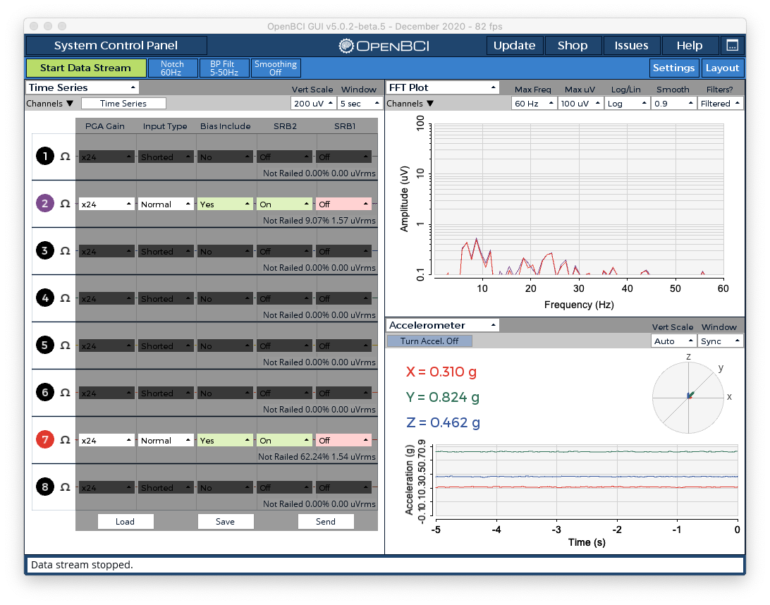
The dropdowns inside the Hardware Settings controller indicate the current settings of the ADS1299 registers on your Cyton board. For more information on these settings, refer to pages 39-47 of the ADS1299 datasheet.
We have simplified the interface through the OpenBCI firmware and OpenBCI GUI to allow easy, real-time interaction with these registers. For more information on this, please refer to our doc page regarding the ADS1299 interface.
By deactivating channels 1, 3, 4, 5, 6, and 8, those channels were automatically removed from the BIAS and SRB2, so as not to interfere with the signal.
e) After updating these settings, click Send to send the updated settings to the board. Then click the Time Series button again to view the data.
4. Alpha brain waves (EEG)
Now, for what we've all been waiting for... let's check out some brain waves!
It's best to do this portion of the tutorial with a friend. You'll understand why in a second. It just so happens that the easiest way to consciously produce brain waves is by closing your eyes. When you do this, your occipital lobe (the part of your brain responsible for processing visual information) enters into an alpha wave state at a frequency between 7.5-12.5 Hz. Alpha brain waves are the strongest EEG brain signal! Historically, they are thought to represent the activity of the visual cortex in an idle state. An alpha-like variant called mu (μ) can be found over the motor cortex (central scalp) that is reduced with movement, or the intention to move [Wikipedia].
For more information on Alpha waves check out Wikipedia and Chip's EEG Hacker blog post about detecting alpha waves with OpenBCI V3.
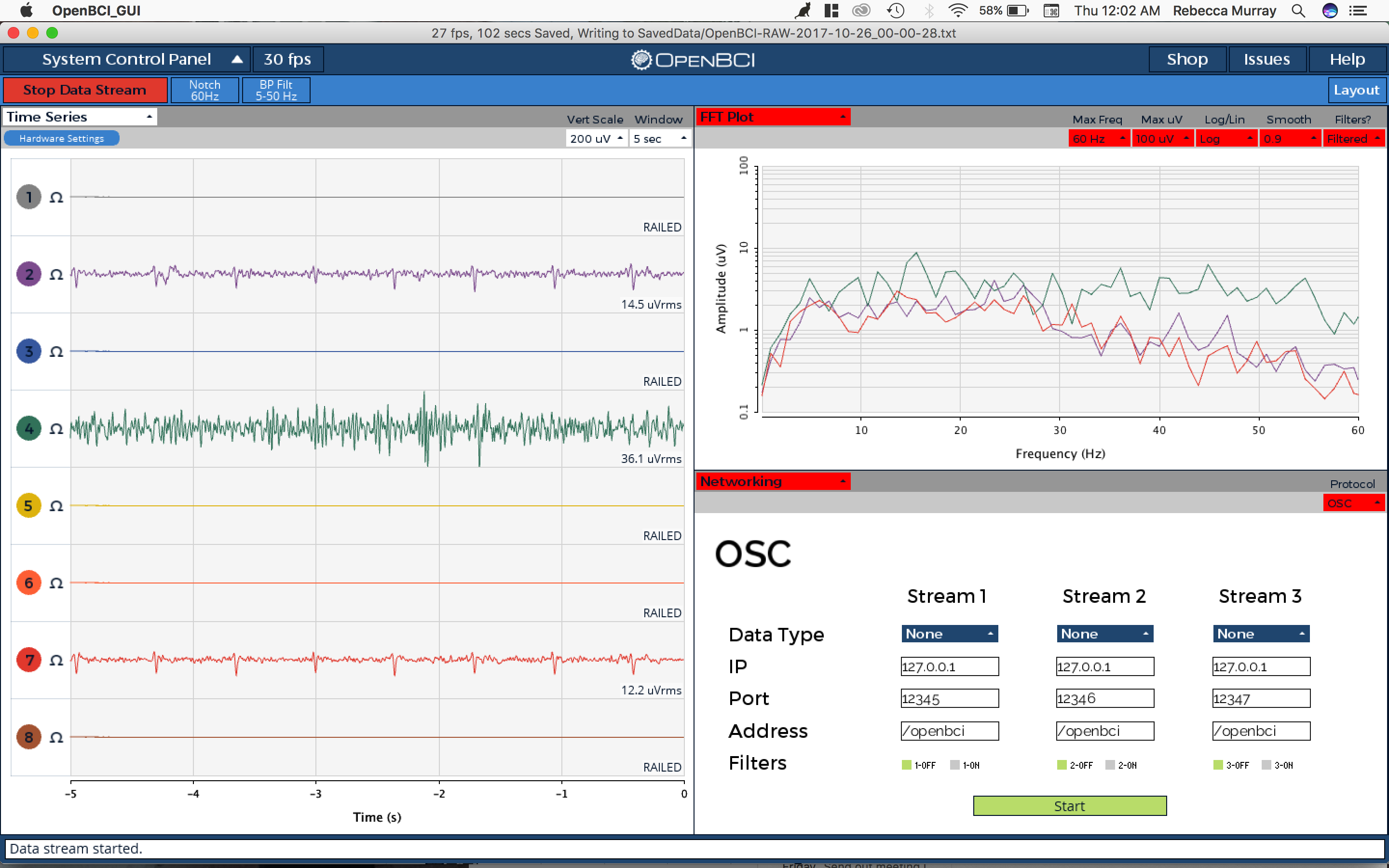
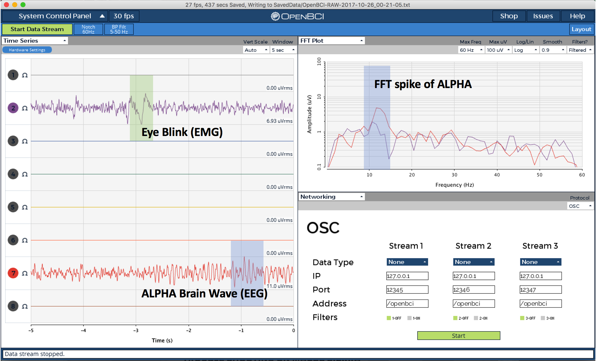
Once you've closed your eyes, have your friend press the 'm' key on your keyboard to take screenshots. Tell him or her to wait until a strong alpha spike emerges on the Fast Fourier Transform (FFT) Graph, the graph in the lower-right of the GUI. The spike should be somewhere between 7.5-12.5 on the the x-asix of the FFT graph, indicating that there is a strong presence of waves in that frequency range.
After you've taken a few good screenshots, open up the .JPGs and take a look. Note: the screenshots are located in the root directory of your application, or in the OpenBCI_GUI directory if you are working from Processing.
You'll notice that the strongest alpha wave signals should be appearing in channel 7, the O2 (O standing for occipital) electrode on the back of your head. Count the number of waves in a single 1-second time period on channel 7 of the EEG DATA montage. The number of waves should correspond x-axis position of the spike on the FFT graph. If you've identified your alpha waves, congratulations! You've now seen your first brain waves with OpenBCI!
Improving Signal Quality
For help minimizing noise and improving the quality of your EEG signals, check out this document