OpenBCI EEG Headband Kit Guide
Now available in our shop!
When combined with our Ganglion, Cyton, or CytonDaisy boards, the OpenBCI EEG Headband Kit is a low-cost, easy-to-use device for obtaining research-grade EEG data.
This tutorial will guide you through setting up your headband kit! Please read this tutorial in its entirety before setting up the system.
Each kit includes:
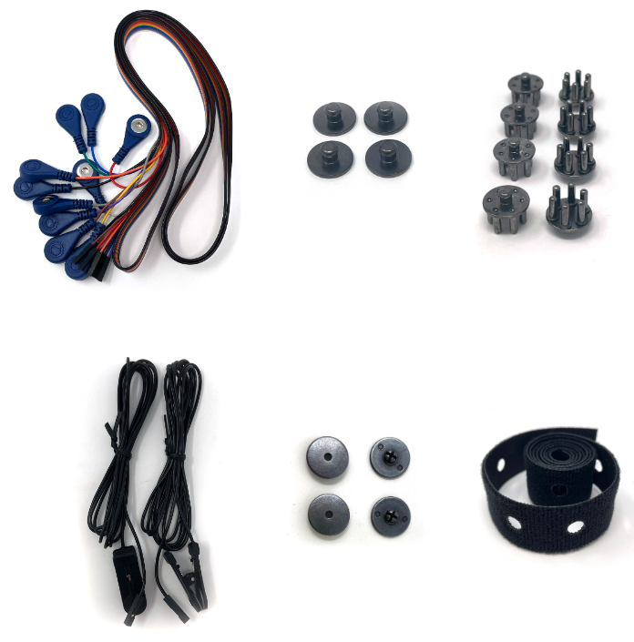
- Pair of Ear-clip electrodes
- Dry comb snap silver-silver chloride coated EEG electrodes
- Dry flat snap silver-silver chloride coated EEG electrodes
- Pack of snap electrode cables
- One adjustable headband strap
- clip to attach your board case to the headband strap (in headband kit 0.5 meter variant)
The comb and flat snap electrodes snap in and out of the cables easily. No tools needed.
All electrode wires end in a 0.1" female header termination compatible with OpenBCI biosensing boards (Ganglion, Cyton, and CytonDaisy).
10-20 Internationally Accepted EEG Node Placement
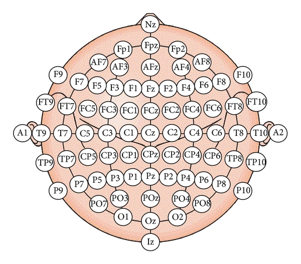
The flat snap electrodes facilitate multiple frontal cortex measurements (F7, AF7, Fp1, Fpz, Fp2, AF8, F8). The comb snap electrodes will allow measurement at the FT7/FT8, T7/T8, TP7/TP8, P7/P8, PO7/PO8, O1/O2, and Oz nodes, depending where on the adjustable strap you place the electrodes. This kit is intended to provide up to eight channels of EEG data when paired with the Cyton 8-channel board. If you want 16-channels, purchase two headband kits and pair them with the CytonDaisy 16-channel board.
Headband-Ganglion Tutorial
The Ganglion board supports four channels of EEG/EMG/EEG input and streams data over bluetooth. In this tutorial we will show you how to obtain two frontal lobe measurements and two temporal lobe measurements using the four channels of the Ganglion and stream the data over bluetooth!
Battery
All OpenBCI boards ship with a compact, rechargeable lithium polymer 3.7V battery and USB charger (or a 2-pin standard JST compatible 4-AA battery holder, pre-2023).
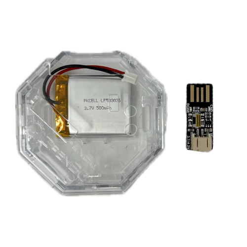
Fully charge the Lithium Polymer Battery, until the charger's indicator LED turns green
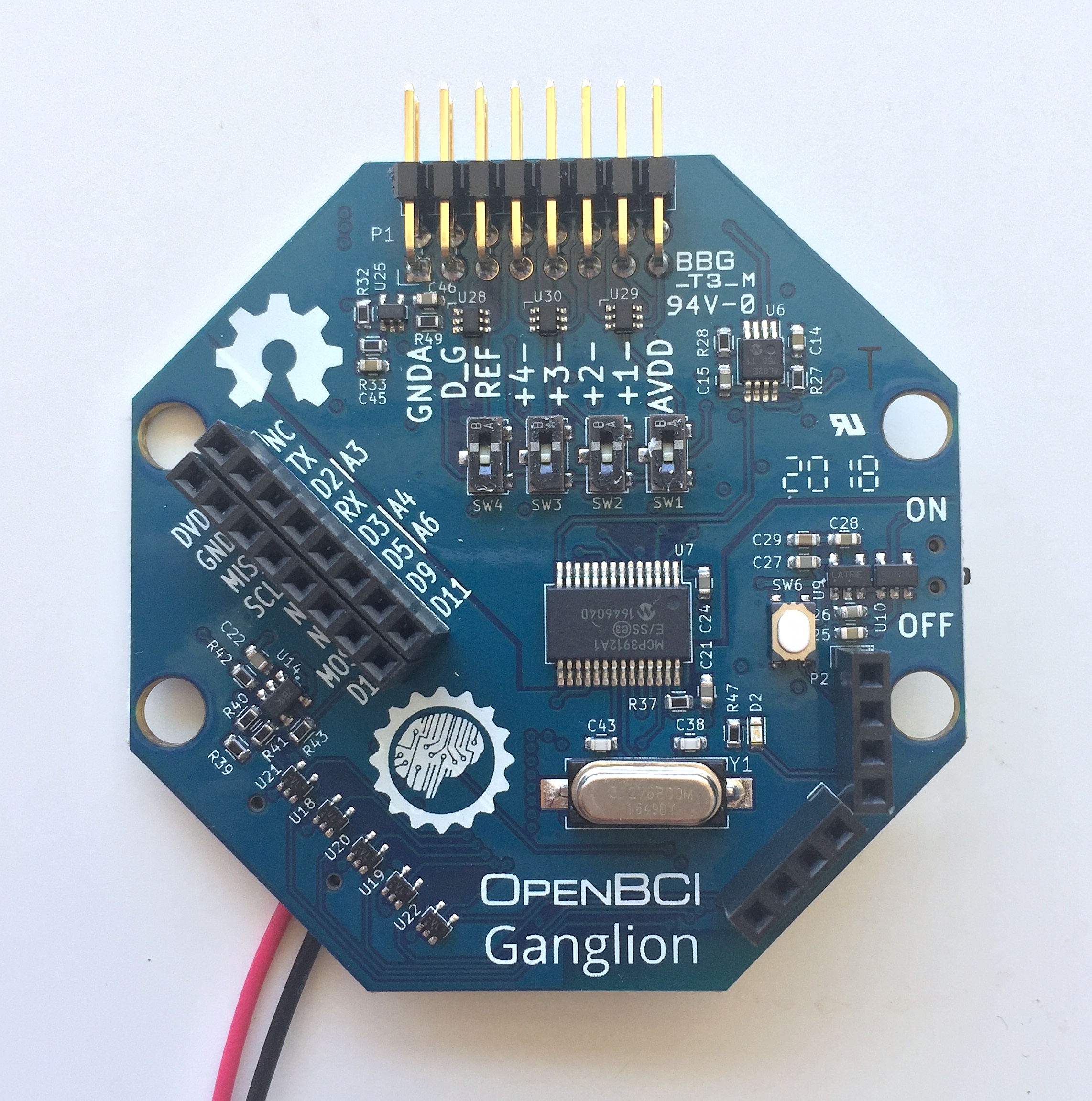
Hardware
Your Ganglion may have shipped with orange protective cellophane over switches sw1 - sw4. After you've peeled the protective layer off, and flipped the switches to down position, the Ganglion board will be in EEG mode (shown below).
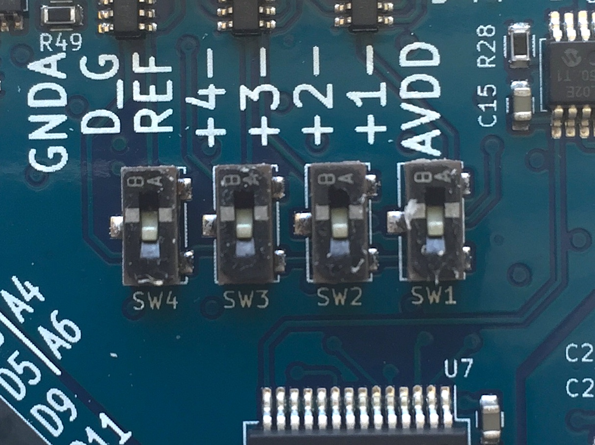
Optional: see the Ganglion Hardware page for a detailed explanation of why we flip the four channel switches to down.
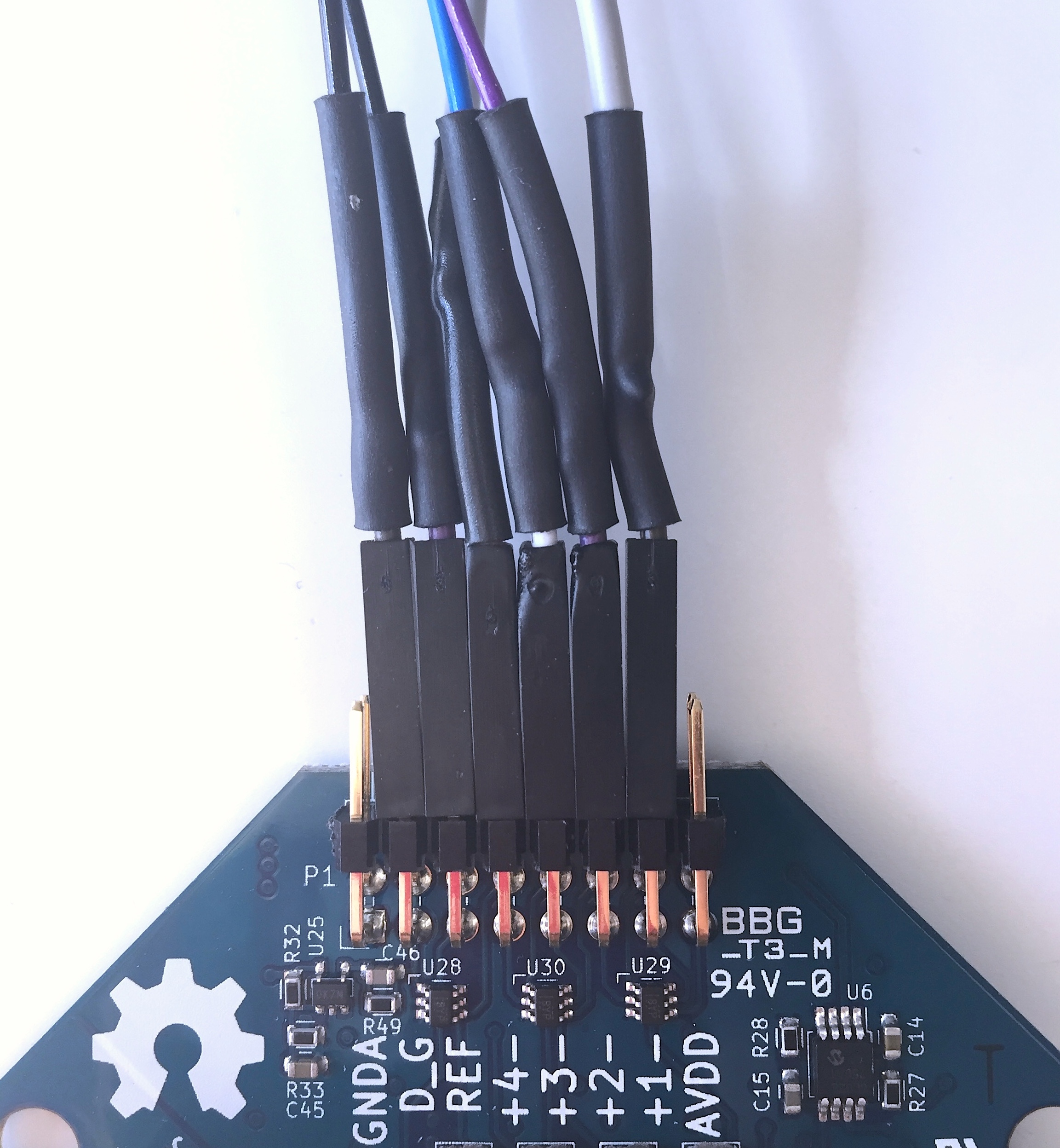
Steps
- Connect one earclip electrode to the top D_G (driven ground) pin, as shown above.
- Connect the second earclip electrode to the top REF pin, as shown above.
- Connect the female terminations of the two flat snap electrodes and two comb electrodes to top pins 1-4, shown above. (The order of pin connections is up to user preference.)
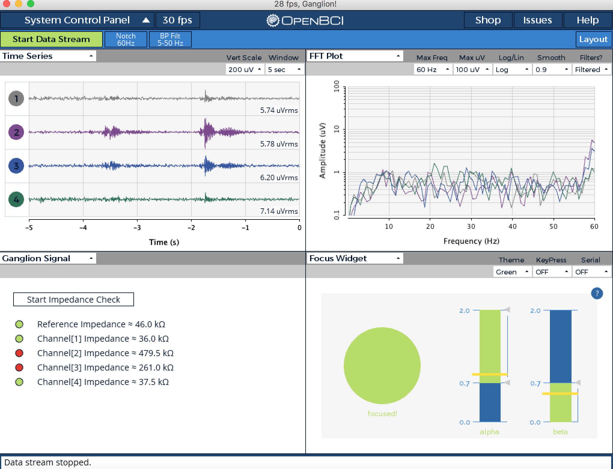
- Place the velcro headband between the snap end of a cable and a snap electrode, making sure to align with the hole in the headband, then press the electrode into place.
| GUI Channel | Electrode | Ganglion Board Pin | Electrode Type |
|---|---|---|---|
| 1 | Fp1 | Top +1 pin | Flat snap |
| 2 | Fp2 | Top +2 pin | Flat snap |
| 3 | TP7 | Top +3 pin | Comb Snap |
| 4 | TP8 | Top +4 pin | Comb Snap |
| - | A1 | Top D_G pin | Ear clip |
| - | A2 | Top REF pin | Ear clip |
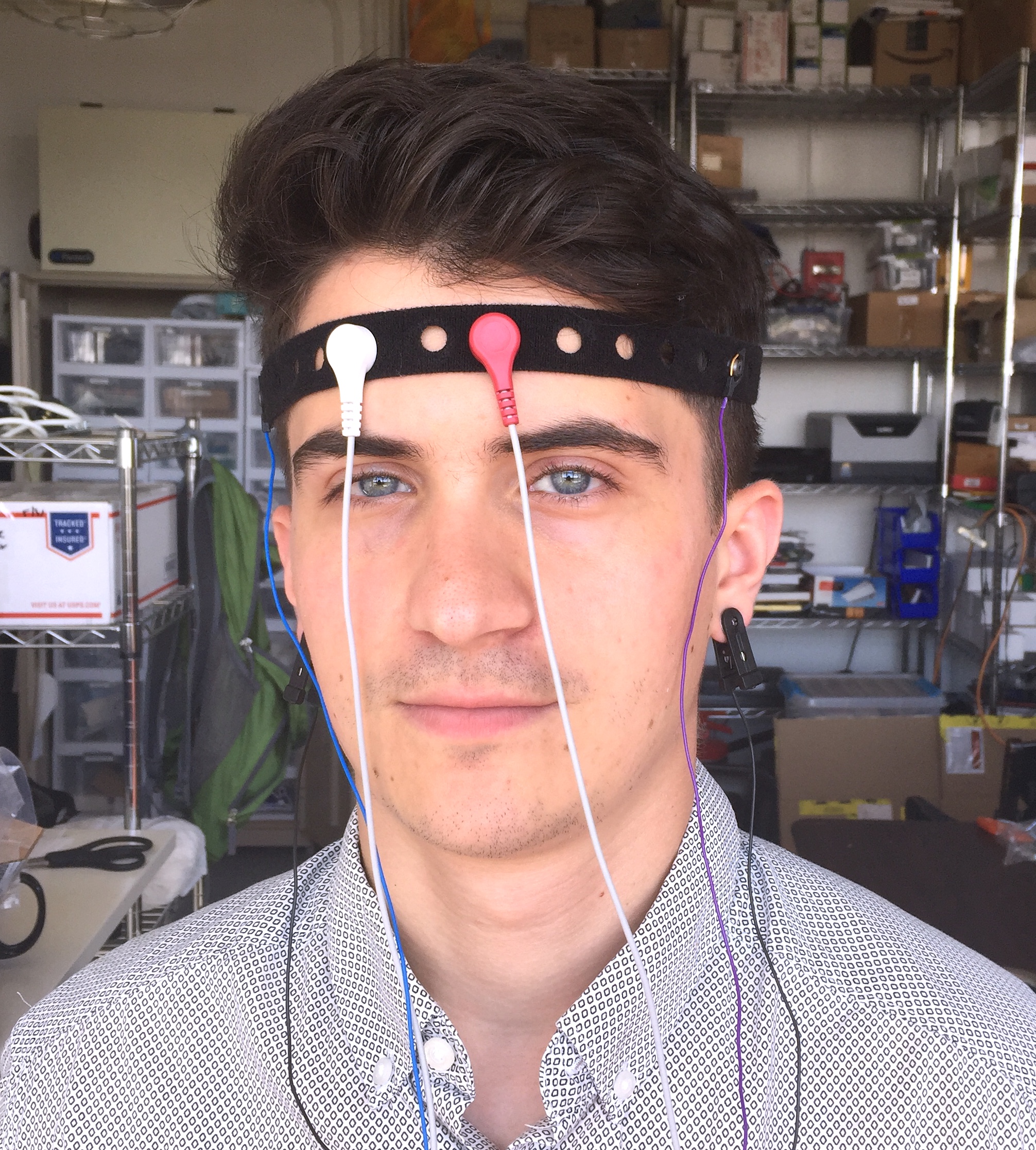
Assembling the Headband
The placement of nodes on the headband is best represented in the following image:
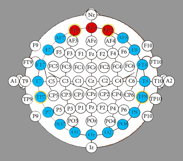
In this diagram, the red circles represent areas where flat electrodes can be placed, and the blue circles represent areas where comb electrodes can be placed. This placement is ultimately up to you, and the areas that you wish to record. However, a general suggestion for standard electrode placement is outlined in yellow.
To attach the electrodes to the headband:
- Place the cable head on the rough side of the velcro
- Place the electrode on the soft side of the velcro
- Snap the two pieces together, with the velcro in between, to secure them.
To attach the OpenBCI board onto the headband (for 0.5 meter variants):
- Snap the clip on the back of the clear board case (bottom half)
- Plug the compact lithium battery into the 2-pin JST on the back of the OpenBCI Board.
- Place your board and battery into the bottom half of the clear case, taking care to position the battery into the compartment
- Snap the top half of the board case onto the bottom, then "hook" the clip on the velcro strap
When worn, the headband strap should fit quite snugly around the head, with the OpenBCI board positioned at the back of the head.
OpenBCI Software
Now that you've finished with the hardware set-up, the next step is to set up the GUI! Follow the GUI tutorial to prepare your computer to communicate with your Ganglion.
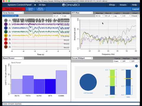
Once you've downloaded the GUI zip file per tutorial instructions, fire up the GUI as shown in this YouTube video!
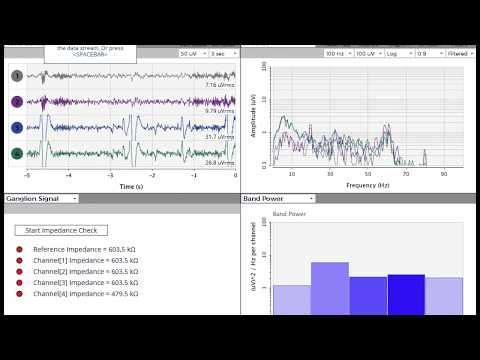
Notice the sharp peak-trough-peak wave behavior in the upper left time series window of the GUI. The first peak corresponds with the initiation of an eye blink, the trough immediately after shows a dip in alpha brain waves that syncs to the eye's closing for a fraction of a second! The peak immediately after the trough corresponds to the brain signals to the eyelid to reopen, thus concluding the blink cycle.
The band power window in the lower right of the GUI shows the relative strengths of the user's alpha, beta, gamma, delta, and theta brain waves. The GUI and Ganglion work together to separate and categorize brain waves based on characteristics like frequency and amplitude.
In the picture above, you can see the Ganglion Signal window in the lower left of the GUI. This widget helps users establish a quality connection for each electrode. For most bioelectrical measurements, you want the skin-electrode contact surface impedance to be low. Two of the four channels show lower impedance (these happen to be the flat snap electrodes that are touching the skin over the frontal cortex). This connection must be good, hence the green light to the left of the impedance value. If the impedance light in the GUI is red, you can improve the connection by making sure the electrodes are secured against the skin and making good contact. You may find it helpful to add a little electrode paste to boost conductivity of the Ag-AgCl coating on the electrodes.
Another widget shown in the picture above is the Focus widget. When the alpha waves are (relatively) high and beta waves are low, the GUI translates this to a focused state. Download the latest GUI 5.x.x with updated Focus Widget.
Headband-Cyton Tutorial
The Cyton board supports eight channels of EEG/EMG/EEG input and streams data over bluetooth. In this tutorial we will show you how to obtain three frontal lobe measurements and five temporal lobe measurements and stream the data over bluetooth!
Battery
All OpenBCI boards ship with a compact, rechargeable lithium polymer 3.7V battery and USB charger (or a 2-pin standard JST compatible 4-AA battery holder, pre-2023).
Fully charge the Lithium Polymer Battery, until the charger's indicator LED turns green.
Hardware
As shown above:
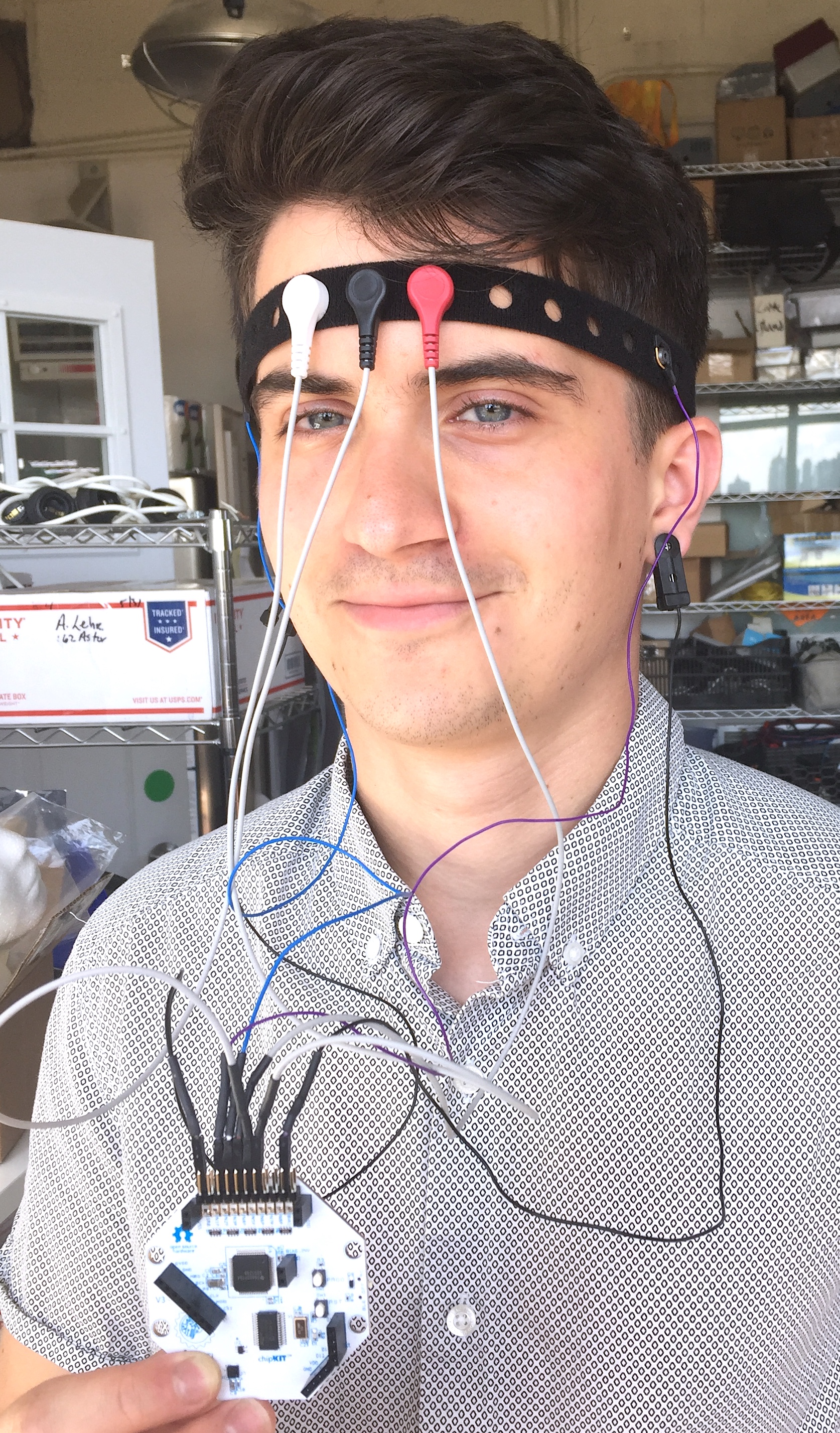
- Connect one earclip electrode to the bottom BIAS pin
- Connect the second earclip electrode to the bottom SRB pin
- Connect the female terminations of the three flat snap electrodes to bottom pins 1-3 (labeled N1P, N2P, and N3P). (The order of pin connections is up to user preference.)
- Connect the female terminations of up to five comb electrodes to bottom pins 4-8 (labeled N4P through N8P). (The order of pin connections is up to user preference.)
- Place the velcro headband between the snap end of a cable and a snap electrode, making sure to align with the hole in the headband, then press the electrode into place.
| GUI Channel | Electrode | Cyton Board Pin | Electrode Type |
|---|---|---|---|
| 1 | Fp1 | Bottom N1P pin | Flat snap |
| 2 | Fp2 | Bottom N2P pin | Flat snap |
| 3 | Fpz | Bottom N3P pin | Flat snap |
| 4 | TP7 | Bottom N4P pin | Comb Snap |
| 5 | TP8 | Bottom N5P pin | Comb Snap |
| 6 | P7 | Bottom N6P pin | Comb Snap |
| 7 | P8 | Bottom N7P pin | Comb Snap |
| 8 | Oz | Bottom N8P pin | Comb Snap |
| - | A1 | Bottom SRB pin | Ear clip |
| - | A2 | Bottom BIAS pin | Ear clip |
Assembling the Headband
The placement of nodes on the headband is best represented in the following image:
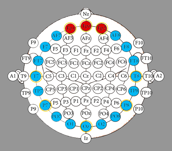
In this diagram, the red circles represent areas where flat electrodes can be placed, and the blue circles represent areas where comb electrodes can be placed. This placement is ultimately up to you, and the areas that you wish to record. However, a general suggestion for standard electrode placement is outlined in yellow.
To attach the electrodes to the headband:
- Place the cable head on the rough side of the velcro
- Place the electrode on the soft side of the velcro
- Snap the two pieces together, with the velcro in between, to secure them.
To attach the OpenBCI board onto the headband (for 0.5 meter variants):
- Snap the clip on the back of the clear board case (bottom half)
- Plug the compact lithium battery into the 2-pin JST on the back of the OpenBCI Board.
- Place your board and battery into the bottom half of the clear case, taking care to position the battery into the compartment
- Snap the top half of the board case onto the bottom, then "hook" the clip on the velcro strap
When worn, the headband strap should fit quite snugly around the head, with the OpenBCI board positioned at the back of the head.
OpenBCI Software
Now that you've finished with the hardware set-up, the next step is to set up the software! Download the OpenBCI GUI to prepare your computer to communicate with your Cyton.
Once you've installed the GUI, fire it up as shown in this YouTube video!
Play around with the vertical scale, filter, frequency range to see the effect on the raw data. The following screenshot shows an example of what your live-streamed brain data might look like.
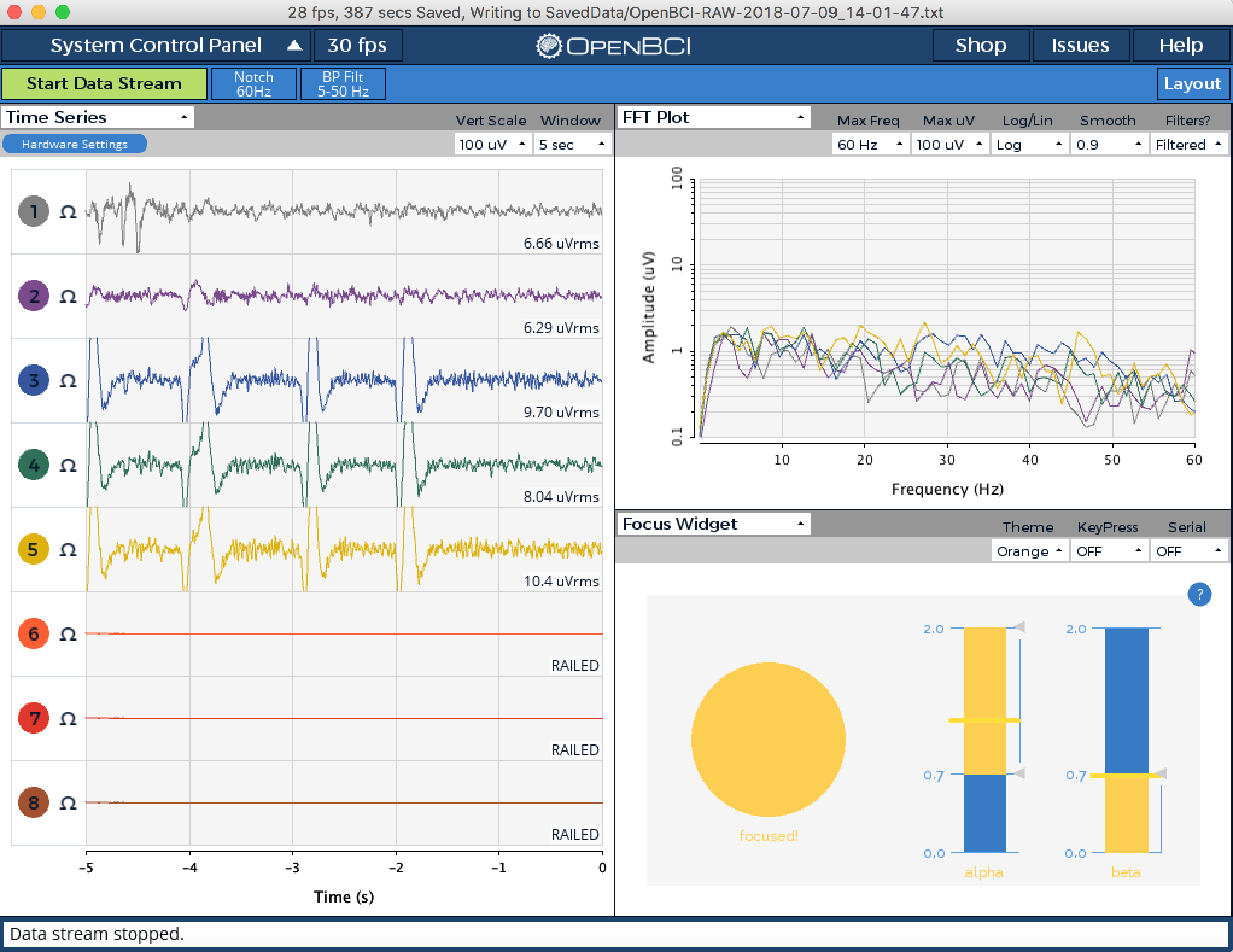
For more details on the various GUI functions, scroll up to the OpenBCI Software section of the Headband-Ganglion Tutorial above.
For cool project ideas, head over to the Example Projects Directory!
Use Cases for OpenBCI GUI
- OpenBCI device owners want to visualize their brainwaves!
- Many of the researchers, hackers and students alike who purchase OpenBCI devices want to use them to acquire data as soon as their device arrives.
- Users use macOS, Windows and Linux to acquire data
- Users want to filter incoming data in real time
- Users want to make their own experiments to test their awesome theories or duplicate state of the art research at home!
- Users struggle to get prerequisites properly installed to get data on their own from OpenBCI Cyton and Ganglion.
- Users want to stream data into their own custom applications such as MATLAB.
Headband Tips and Signal Troubleshooting
Steps to fix RAILED error in the GUI Time Series widget:
- Open the GUI and hit ‘Start Session’
- Before streaming data, open Hardware settings
- Set Gain to 8x or 12x, then hit ‘send’
- hit 'Start Streaming'
If you are seeing RAILED error, the default gain 24x may be too high for you. The optimal gain will vary depending on the individual user’s skin impedance.
General suggestions
- Moisten a Q-Tip in rubbing alcohol, and scrub the surface of the head directly underneath the contact point for each electrode. This will remove oil/debris from the skin, resulting in a better signal. Then place the headband on the head, with the center electrode in the center of the forehead.
- Optional - The flat and snap electrodes can be used with electrode gel. Inject electrode gel into the contact area using any standard small syringe. This will improve signal quality by lowering the skin-electrode impedance.
- We recommend using a thin, flat tool to remove the flat snap electrodes. Un-snap it with the help of a thin screwdriver.
What You Can Do with OpenBCI GUI and Software Stack
- Visualize data from every OpenBCI device: Ganglion, Cyton, CytonDaisy.
- Playback files using GUI.
- Download as a native application on macOS, Windows, and Linux.
- Apply filters and other data processing tools to quickly clean raw data in real time.
- Use the GUI as a networking system to move data out of GUI into other apps over UDP, OSC, LSL, and Serial.
- Send data to MATLAB, Neuropype (using LSL), and other third-party softwares.
- Analyze data with Python and Brainflow
- Create a widget framework that allows users to create their own experiments.
- Output data into a saved file (file format .txt, .csv, .bd/.edf) for later offline processing.
- Customize the layout, change the gain, toggle on/off, check impedance of individual channels of the CytonDaisy board (or any connected OpenBCI board) directly in the GUI!
- Access built-in widgets such as Focus Widget, Band Power, Accelerometer, EEG Head Plot, and MUCH more
As always, don't hesitate to email us at support@openbci.com for assistance!