Ultracortex Mark IV
Development Period: January 2016 Through the Present
Complete Ultracortex Mark 4 kits are available for sale in the OpenBCI Online Store!
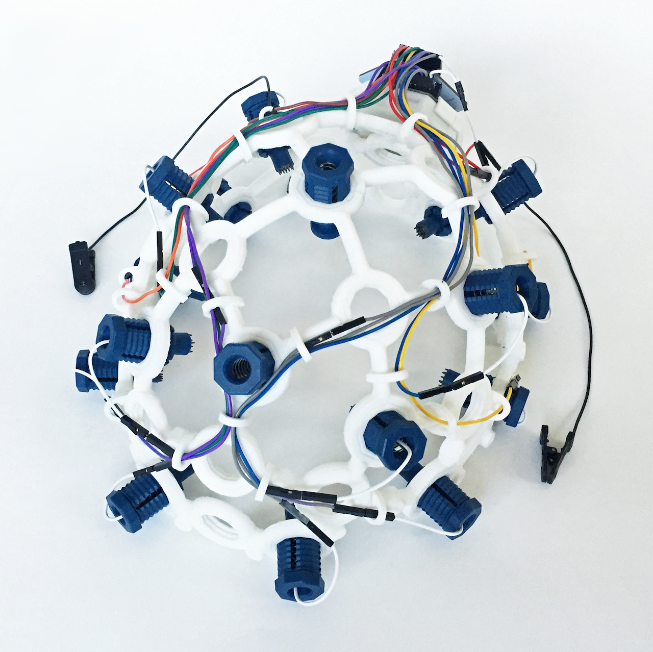
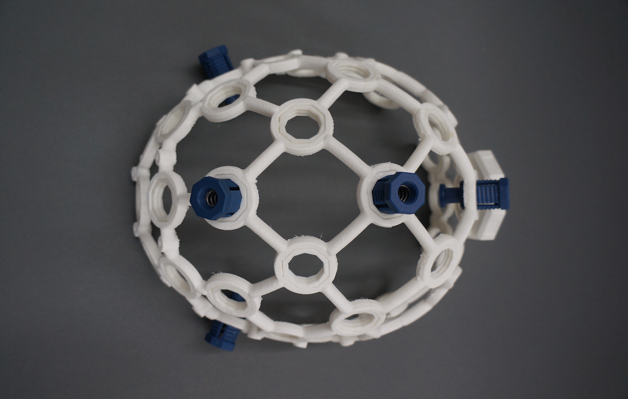
The Ultracortex is an open-source, 3D-printable headset designed to work with OpenBCI Biosensing Boards. It is a tool for recording research-grade brain activity (EEG). The Ultracortex is under constant iteration.
Step-by-step Assembly Tutorial Video
Designers & Engineers:
- Tangible Creative NYC
- Aaron Trocola (aka Threeform)
- Conor Russomanno
- Joel Murphy (aka SafeForRobots)
For those who want to modify the headset design and need CAD files, go to the Ultracortex Mark IV Dev Kit.
THE COMPLETE ULTRACORTEX
Note: the part quantities listed below assume you are making an electrode holder for all 35 nodes of the Ultracortex Mark 4. In reality, you will likely have only 8 or 16 electrodes, depending on whether you are working with the OpenBCI Cyton Board (8 channels) or the OpenBCI CytonDaisy Board (16 channels). In general, more electrodes will distribute the downward scalp pressure, increasing comfort.
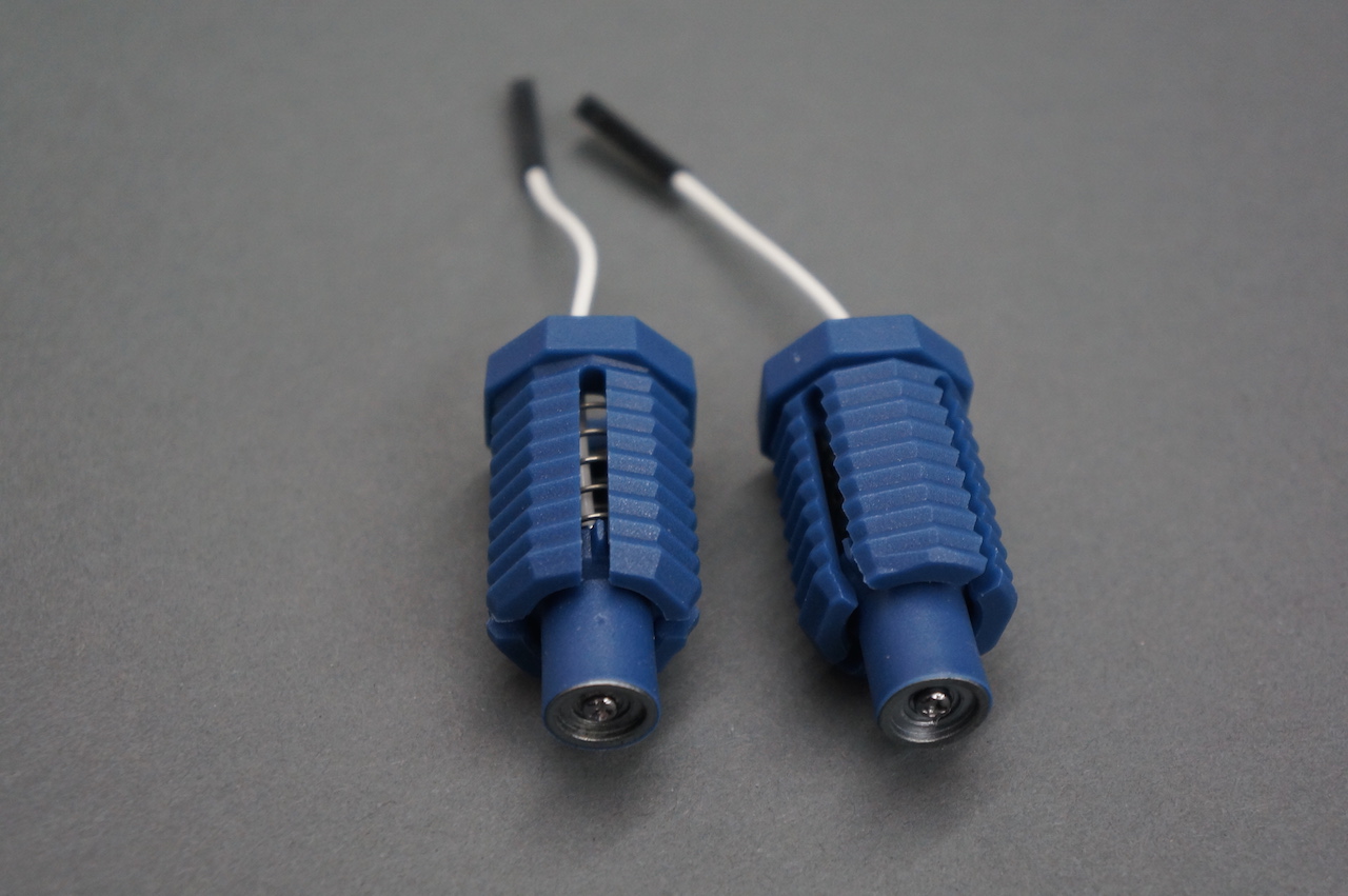
IMPORTANT - PLEASE NOTE before adjusting/twisting the blue electrode mounts, you must disconnect them from their colored cable. Before turning the blue electrode mount in the Ultracortex printed frame, it is NECESSARY to ensure that the white cable end of the electrode mount is free, i.e. not connected to anything. Otherwise, a broken wire is almost guaranteed after repeated turn adjustments. This is not covered by warranty.
3D-printed Parts
The following parts are included in the Unassembled version of the Mark IV:
- FRAME (head circumference: small = 42-50cm, medium = 48-58cm, large = 58-65cm)
- MECH_PARTS
- BOARD_MOUNT (x1) — .STL download link
- BOARD_COVER (x1)
- WIRE_CLIPS (x30)
- WIRE CLIPS (Clips will be used to hold wire in place) — .STL download link
Non-printed Parts:
Note that unlike the Mark III, the electrodes and the electrode holders of the Mark IV are not designed to be 3D printed. The Spikey, Flat, and Comfort Units are all custom made and injection molded and can be purchased at the OpenBCI shop. If you need thse files for prototyping you can find them here.
The following parts are included in the Unassembled and the Print it Yourself versions of the Mark IV:
-
No.6 screws for brittle plastic (2x).
-
Cables (x3)
- We strip apart the cables in your kit.
-
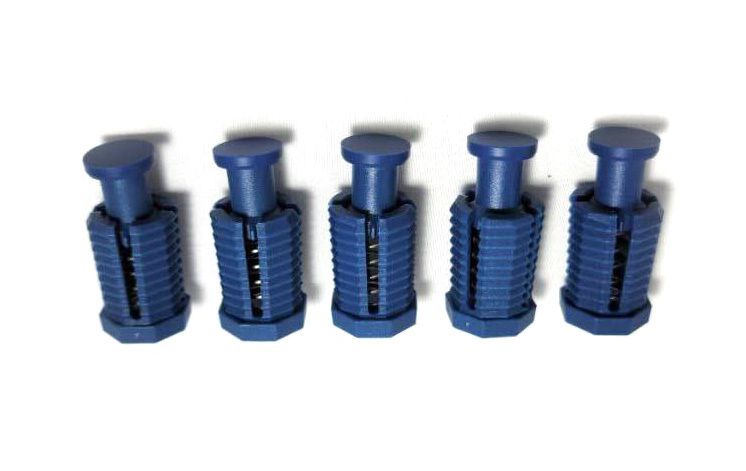
Spikey units
- (6x or 14x) Depending on a 8 or 16 channel heas set dry (spikey) electrodes to be installed in Ultracortex nodes with hair.
-
Flat units
- (2x) Dry (non-spikey) electrodes to be installed in Ultracortex nodes without hair (forehead, for instance).
-
Comfort units
- (5x) Comfort units used for distributing of headset weight equally.
-
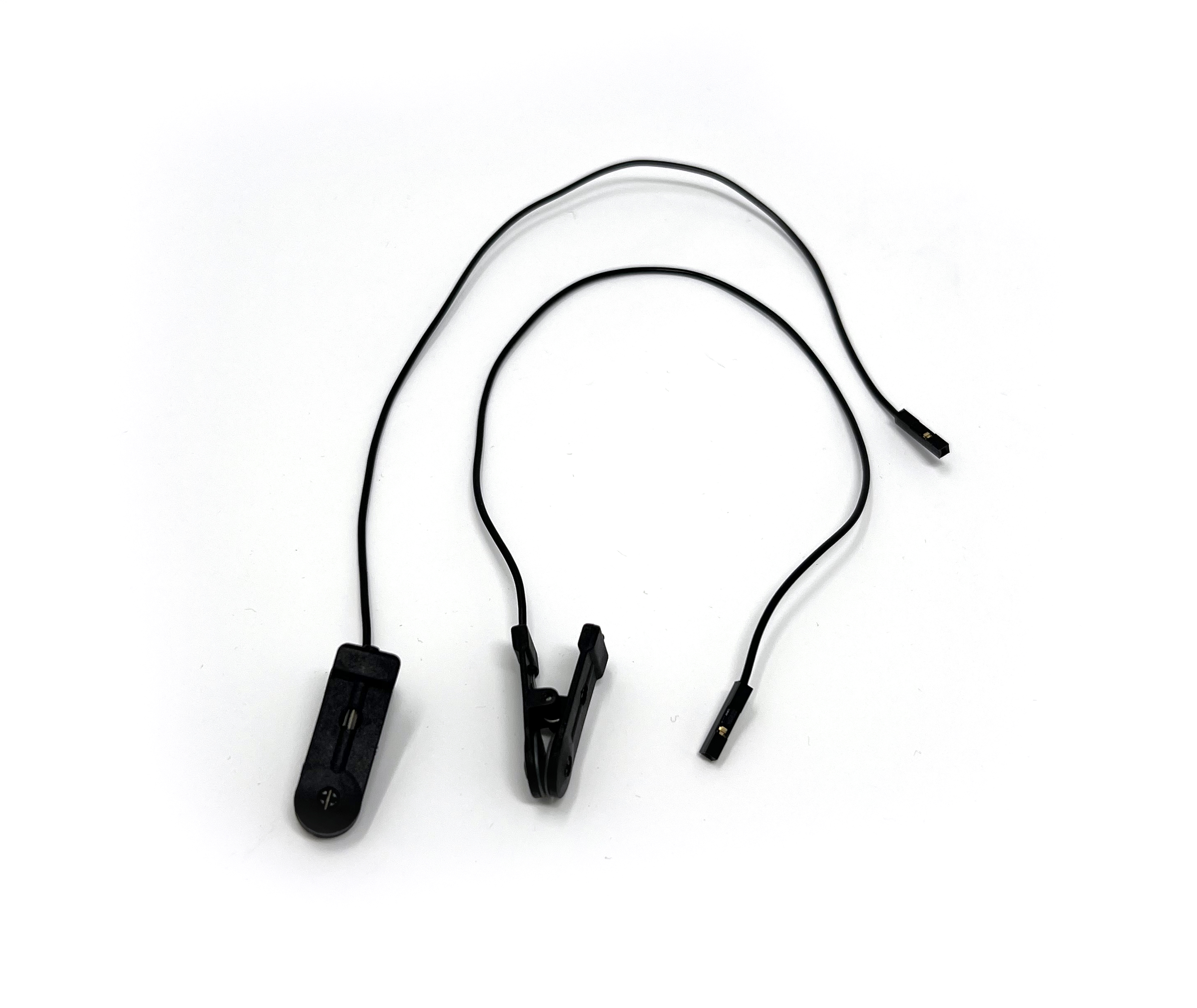
Ear Clips
- (2x) Ear Clip electrode.
The following parts are not included with the purchase of any configuration of the Mark IV and should be purchased separately:
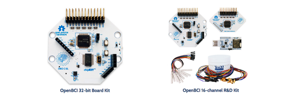
- An OpenBCI Cyton 8-channel Board or an OpenBCI CytonDaisy 16-channel Board (1x)
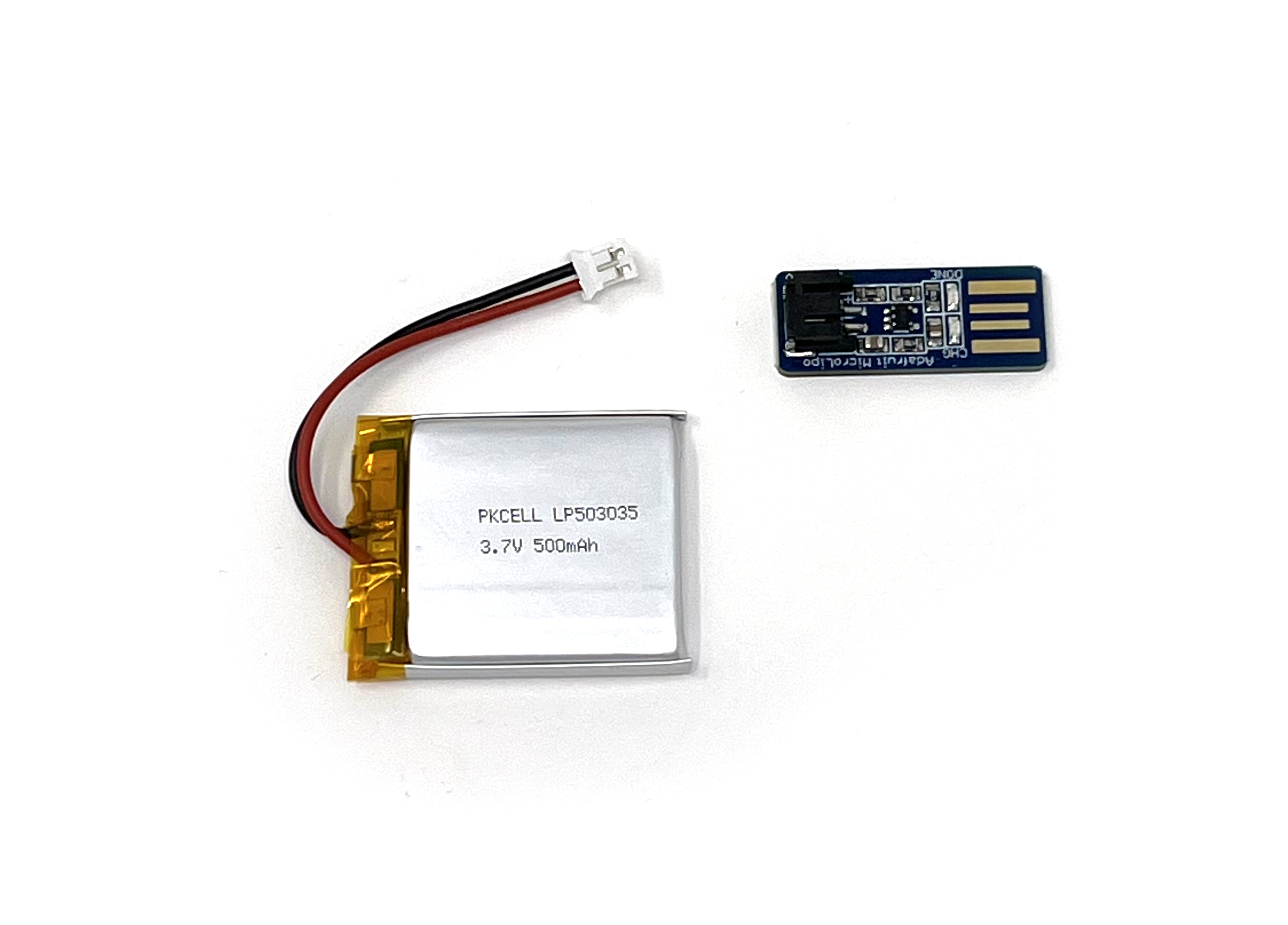
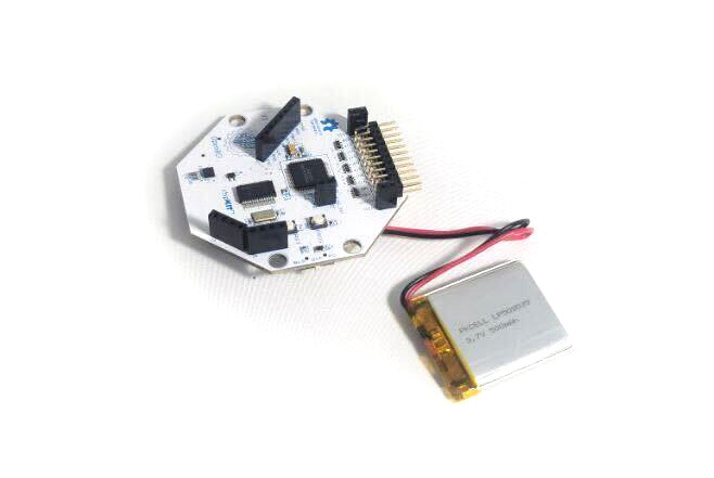
- Lithium Ion Rechargeable Battery Pack (~500mAh) — Sparkfun or Adafruit (1x)
- A charger for your battery pack (1x)
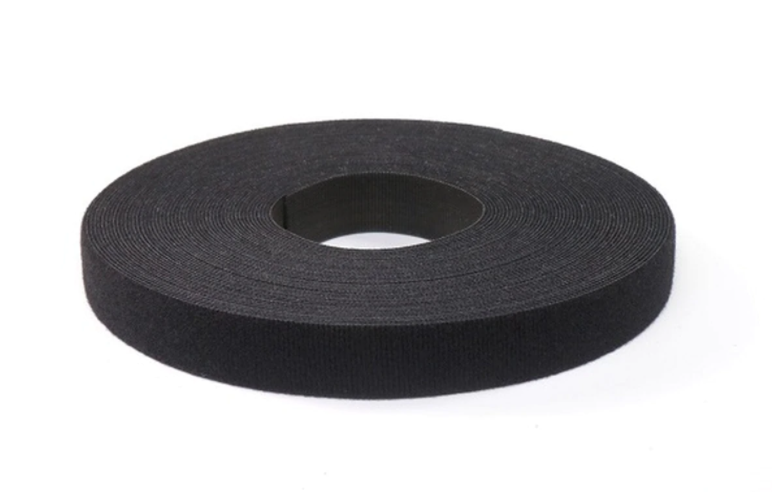
- Velcro One Wrap (1x)
THE COMPLETE ULTRACORTEX (w/ PICTURES)
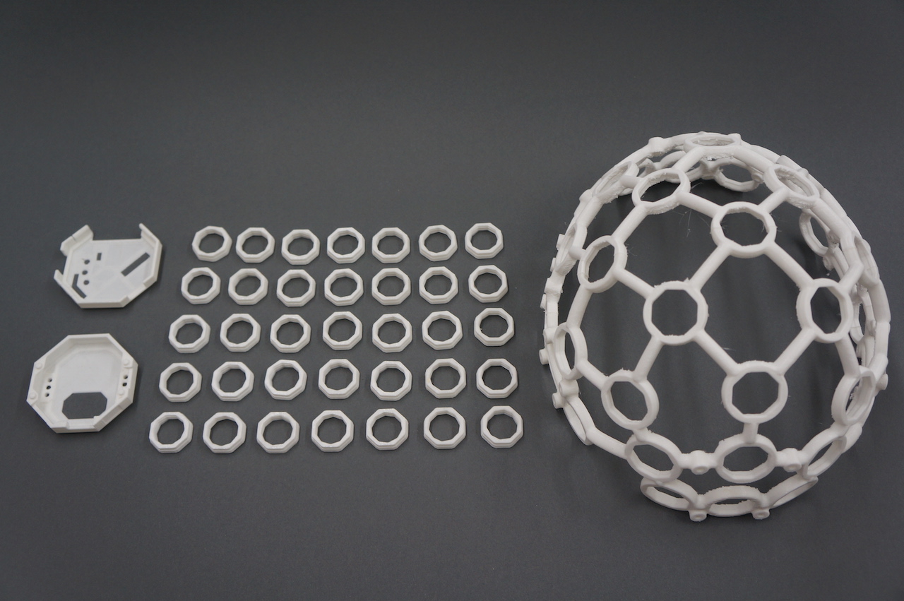
3D-printed Parts:
(1x) FRAME
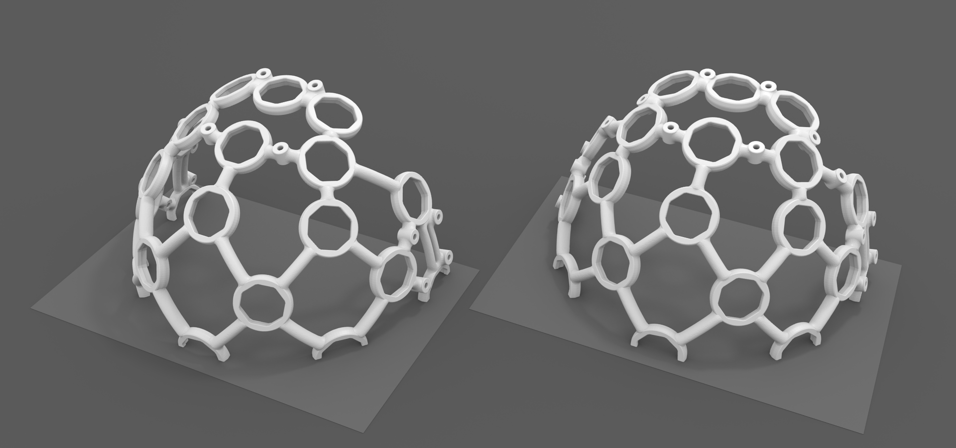
The Ultracortex Mark IV frame is designed to be printed one half at a time (front and back halves), with the flat side on the 3-D printer's build plate. Prusa and Lulzbot make 3-D printers that are suitable for printing the Mark IV frame in halves or quarters. Because printing requires margin for support material, we recommend a printer with a build area of 250 mm by 250 mm. The absolute minimum build area needed to print the frame in halves is 130 mm by 210 mm square.
- FRAME (head circumference: small = 42-50cm, medium = 48-58cm, large = 58-65cm)
The image below shows the correct 3-D printing orientation of the Ultracortex Mark IV frame halves. Please note how the flat sides (halved nodes) sit on the light gray build plate. The halved nodes are completely flat on the edge, so they are properly supported when in contact with the build plate. The model must be positioned correctly in the 3D print preparation software. The flat side of the model should face downward, on the platform. If it does not fit, view it from below and move/rotate the model. The model must be printed with support and a brim or raft. The headset is designed to be printed using FDM extrusion.
(21x) MECH_PARTS
(1x) BOARD_HOLDER
- BOARD_MOUNT (x1) — .STL download link
(1x) BOARD_COVER
- WIRE CLIPS (lips will be used to hold wire in place) — .STL download link
Non-printed Parts:
Note that unlike the Mark III, the electrodes and the electrode holders of the Mark IV are not designed to be 3D printed. The Spikey, Flat, and Comfort Units are all custom made and injection molded and can be purchased at the OpenBCI shop. If you need these files for prototyping you can find them here.
Suggested screws for fastening BOARD_MOUNT & OpenBCI Board
-
No.6 screws for brittle plastic (2x):

-
Cables (x3)
- We strip apart the cables in your kit:
-
Spikey units
- (6x or 14x) quantity depending on a 8 or 16 channel headset, dry (spikey) electrodes to be installed in Ultracortex nodes with hair:
-
Flat units
- (2x) Dry (non-spikey) electrodes to be installed in Ultracortex nodes without hair (forehead, for instance):
-
Comfort units
- (5x) Comfort units used for distributing weight of headset:
-
Ear Clips
- (2x) Ear Clip electrode:
The following parts are not included with the purchase of any configuration of the Mark IV and should be purchased separately:
- Velcro One Wrap (1x) - The Ultracortex Mark IV has horizontal bars designed to hold straps. The addition of DIY chin straps improves stability and therefore quality of the signal. We recommend 25 yard rolls of 1" Velcro One Wrap. which has hooks on one side and loops on the other.
SUGGESTED PRINT SETTINGS
If you're 3D-printing your Mark IV yourself, here are the print settings we recommend:
FRAME_FRONT & FRAME_BACK
- Material: PLA
- Supports: YES
- Raft: hopefully NO (but if supports aren't sticking, try the raft)
- Infill: 20%
- Layer Height: 0.2mm
- Number of Shells: 3
- Speed while extruding: 50-70% (slow it down if possible; these parts are detailed)
MECH_PARTS (INSERT)
- Material: PLA
- Supports: NO
- Raft: NO
- Infill: 20%
- Layer Height: 0.2mm
- Number of Shells: 3
- Speed while extruding: 50-70% (slow it down if possible; these parts are detailed)
BOARD_MOUNT, BOARD_COVER
- Material: PLA
- Supports: NO
- Raft: NO
- Infill: 20%
- Layer Height: 0.2mm
- Number of Shells: 3
- Speed while extruding: 50-70% (slow it down if possible; these parts are detailed)
ADDITIONAL TIPS FOR A SUCCESSFUL PRINT
The Ultracortex frame is detailed and can be challenging to print, so we strongly recommended that the operator be experienced enough to determine how settings need to be changed for their machine. That being said, here are some good general tips:
- Print a tall test model such as a figurine with overhanging features (limbs) to ensure your machine is working properly.
- Don't use too much support. Default settings in CURA usually work, but Prusa is heavy on support and makes the headset hard to remove without breaking.
- Print the headset in two halves with the flat sides on the printer bed, as mentioned previously in this document. Use a brim around the edges if your printer has peeling problems. The brim takes extra work to remove but increases likelihood of success. The parts are designed to print at this orientation with least support.
- Here are other tips in order of importance.
- Print slowly, about 50% of default speed, and run the extrusion hotter than normal. 220 degrees is recommended.
- Print using a support raft.
- Print in a warm environment to reduce the shrinkage of the part as it cools.
- Use PLA material (not ABS) and a heated bed.
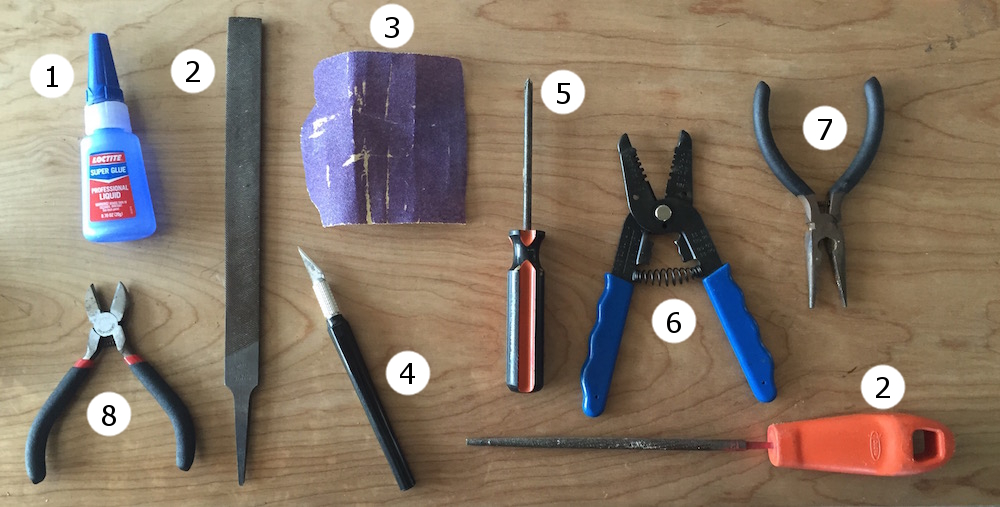
RECOMMENDED ASSEMBLY TOOLS
- Loctite Super Glue w/ Cyanoacrylate
- coarse flat & circular files (for removing support artifacts)
- medium sand paper
- exacto blade
- philips head screw driver
- wire cutters
- needle-nose pliers
- snippers
ASSEMBLY INSTRUCTIONS
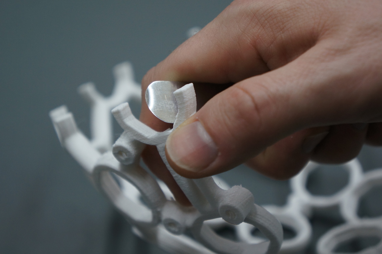
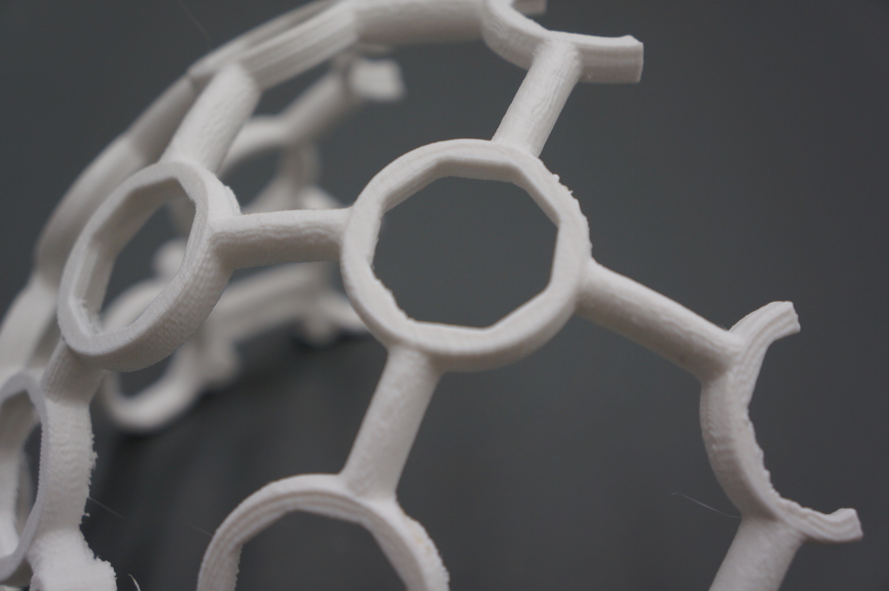
Remove residual support material & print flaws
Use sand paper, a file, and snippers to clean your FRAME and other 3D-printed parts. The most important part of this process is that you thoroughly clean out the frames nodes where you will place your INSERTS pieces.
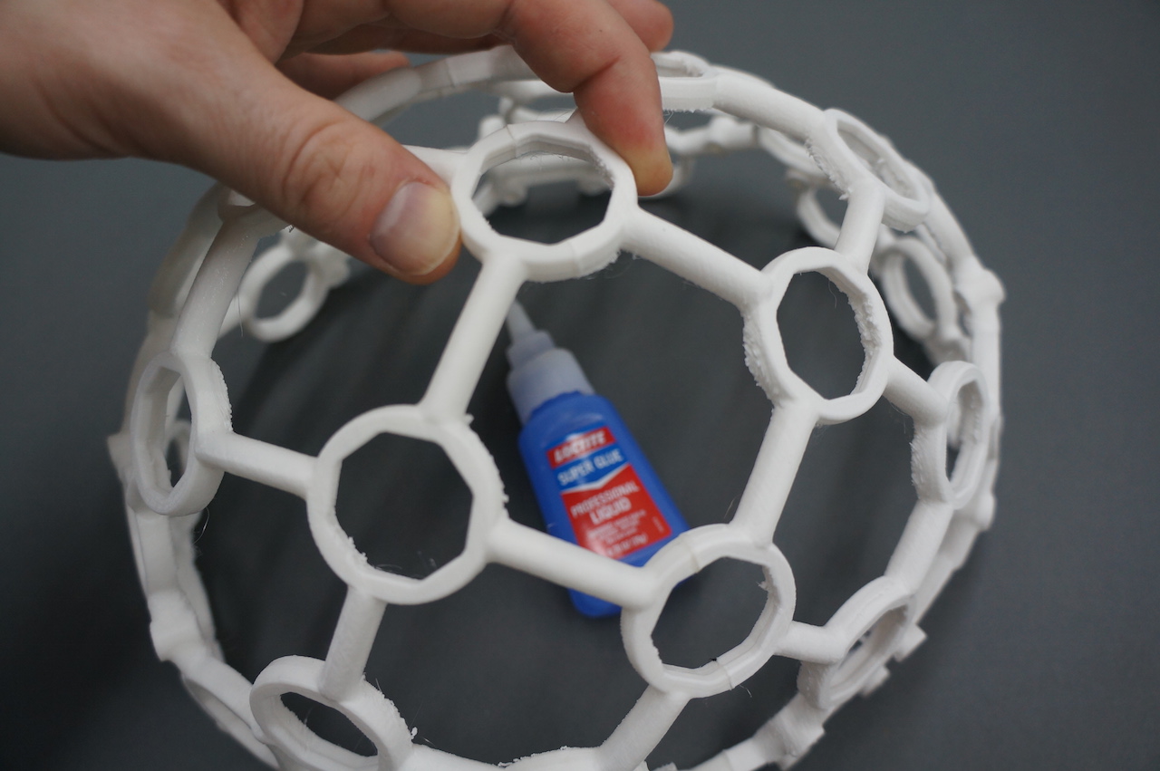
Glue the FRAME together
Carefully, glue the FRONT FRAME and BACK FRAME together with your Cyanoacrylate super glue. The best way to do this is to place both halves of the frame on a level surface and carefully bring them together. Be sure to be precise; it's VERY difficult to pull the pieces apart once you've put them together.
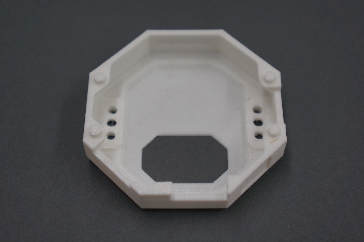
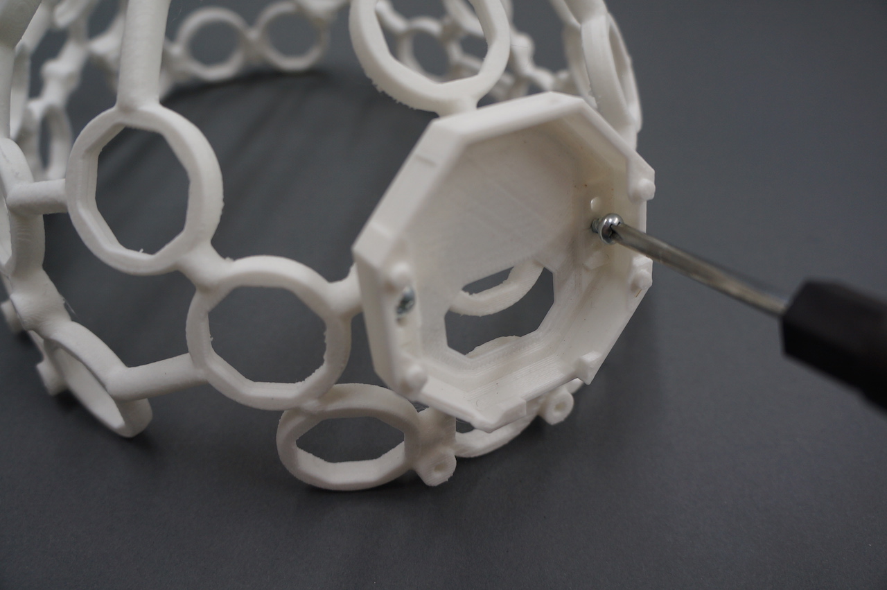
Mount the OpenBCI BOARD_MOUNT
Use two screws to mount the Mark IV Board_Mount to the back (the more rounded half) of the Frame. Make sure that the orientation of the BOARD_HOLDER matches that of the pictures below:
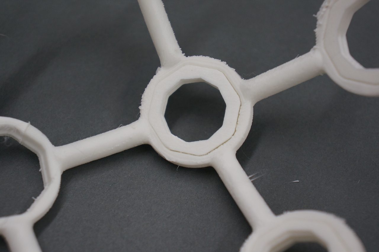
Insert INSERTS pieces (x35) into frame
Before glueing the INSERTS into the frame, ensure that they fit properly into the frame without glue. INSERTs should be inserted from the inside of the frame outwards, so that they lie flush with the frame.
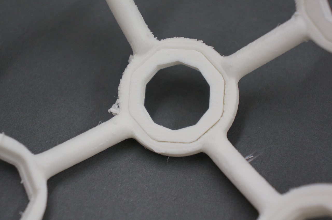
For each INSERT, line the inner rim of the frame with glue. Then insert the INSERT so that it is flush with the frame.
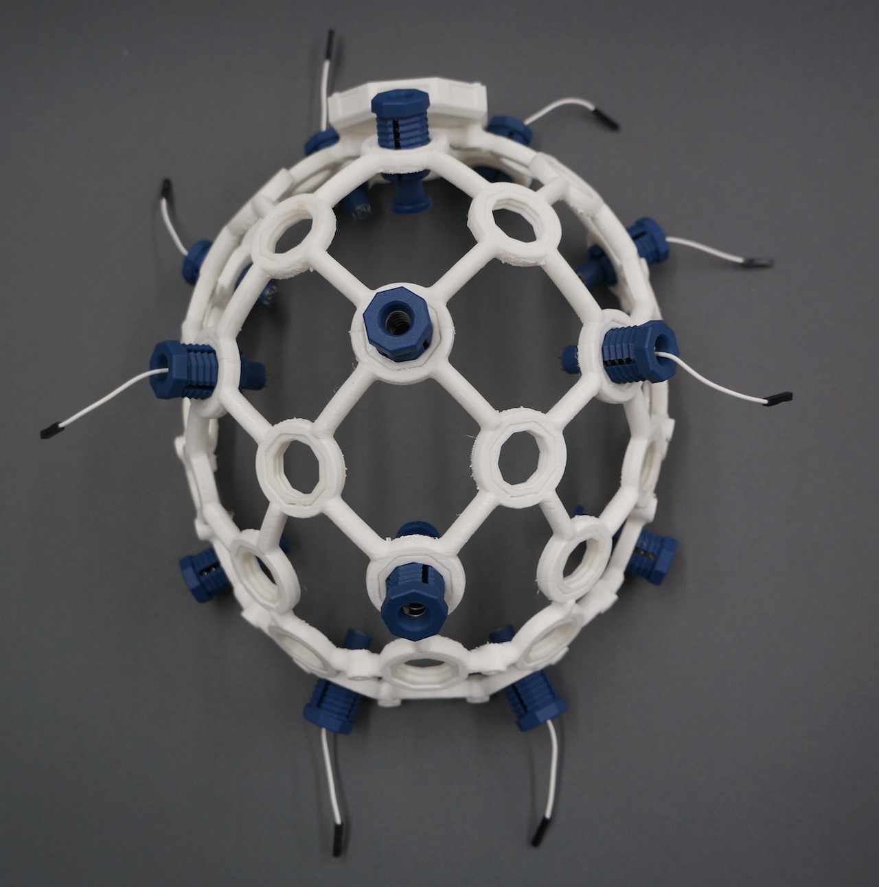
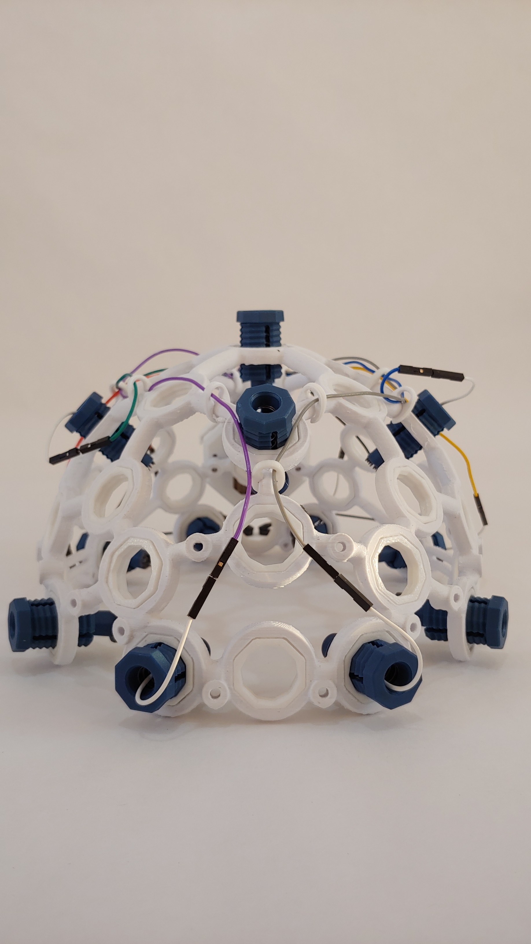
Screw 5 COMFORT UNITS into the frame as shown below. Your Ultracortex should now look like this:
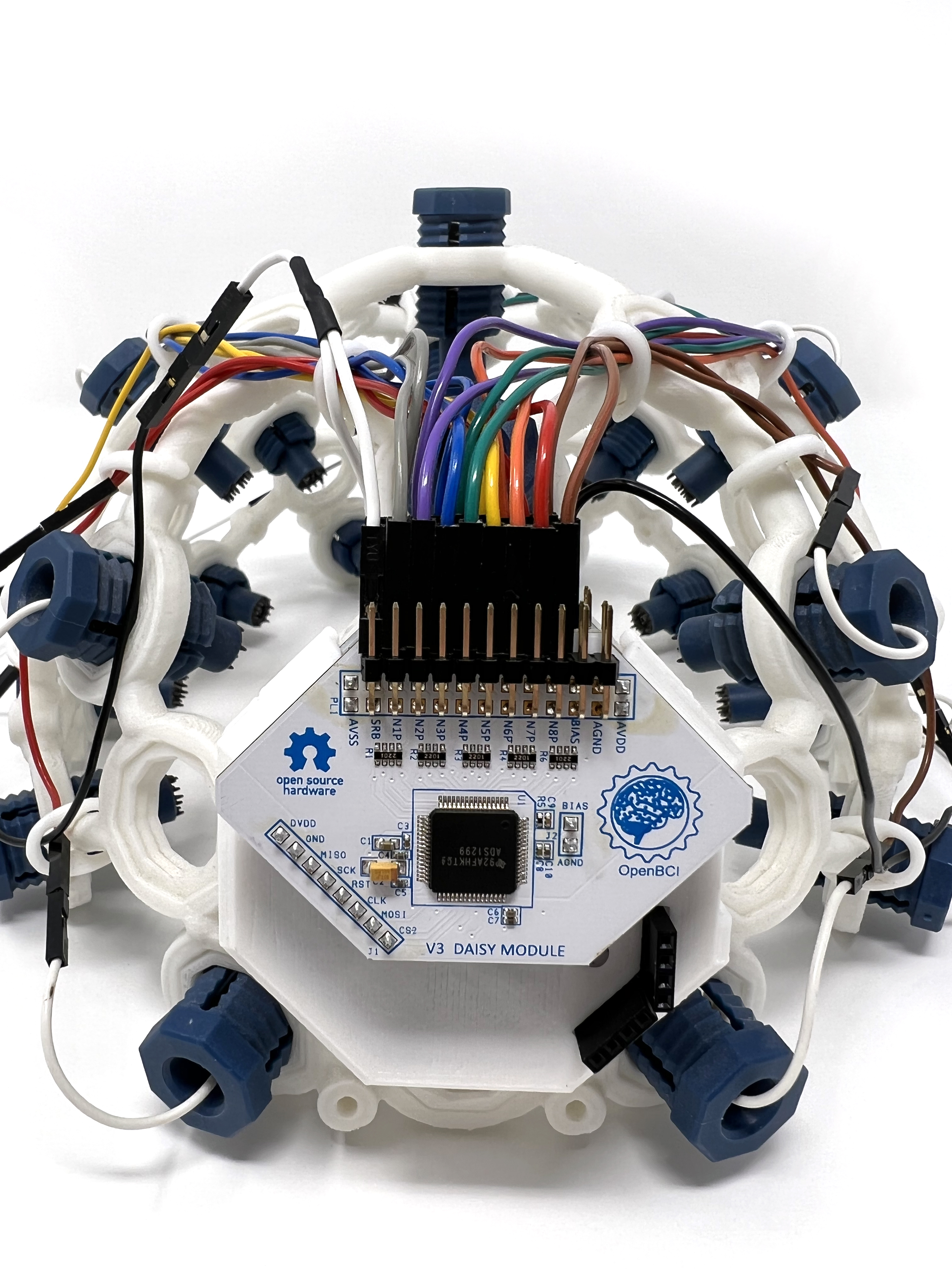
Embed OpenBCI into the Ultracortex
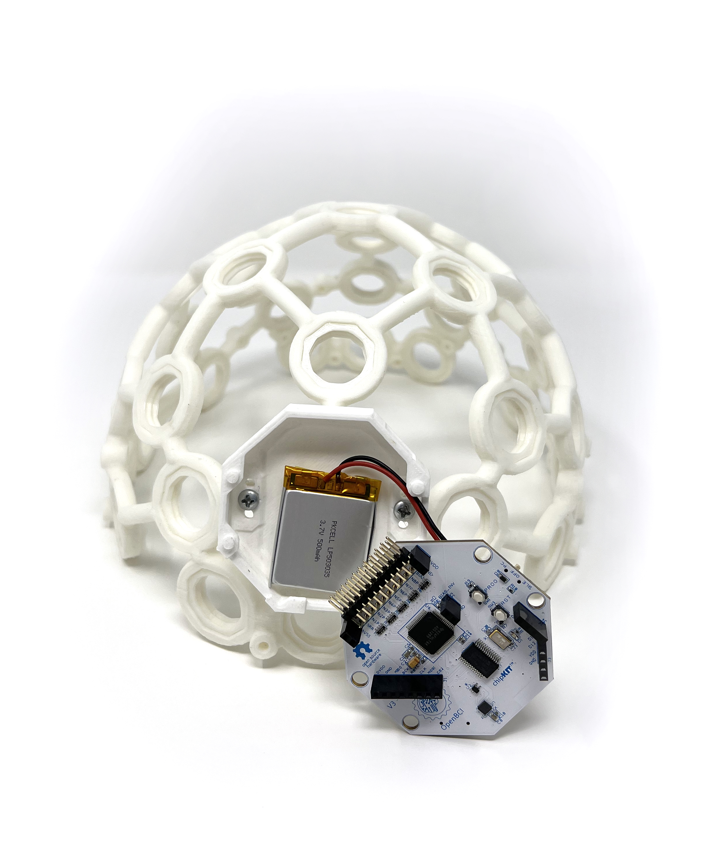
Connect your ~500 mAh lithium ion rechargeable batter to the back of your Cyton OpenBCI Board:
Fold the battery and its wires neatly behind the board before inserting the board into the BOARD_MOUNT:
Snap your Cyton board onto the four pegs on the outside of the BOARD_MOUNT:
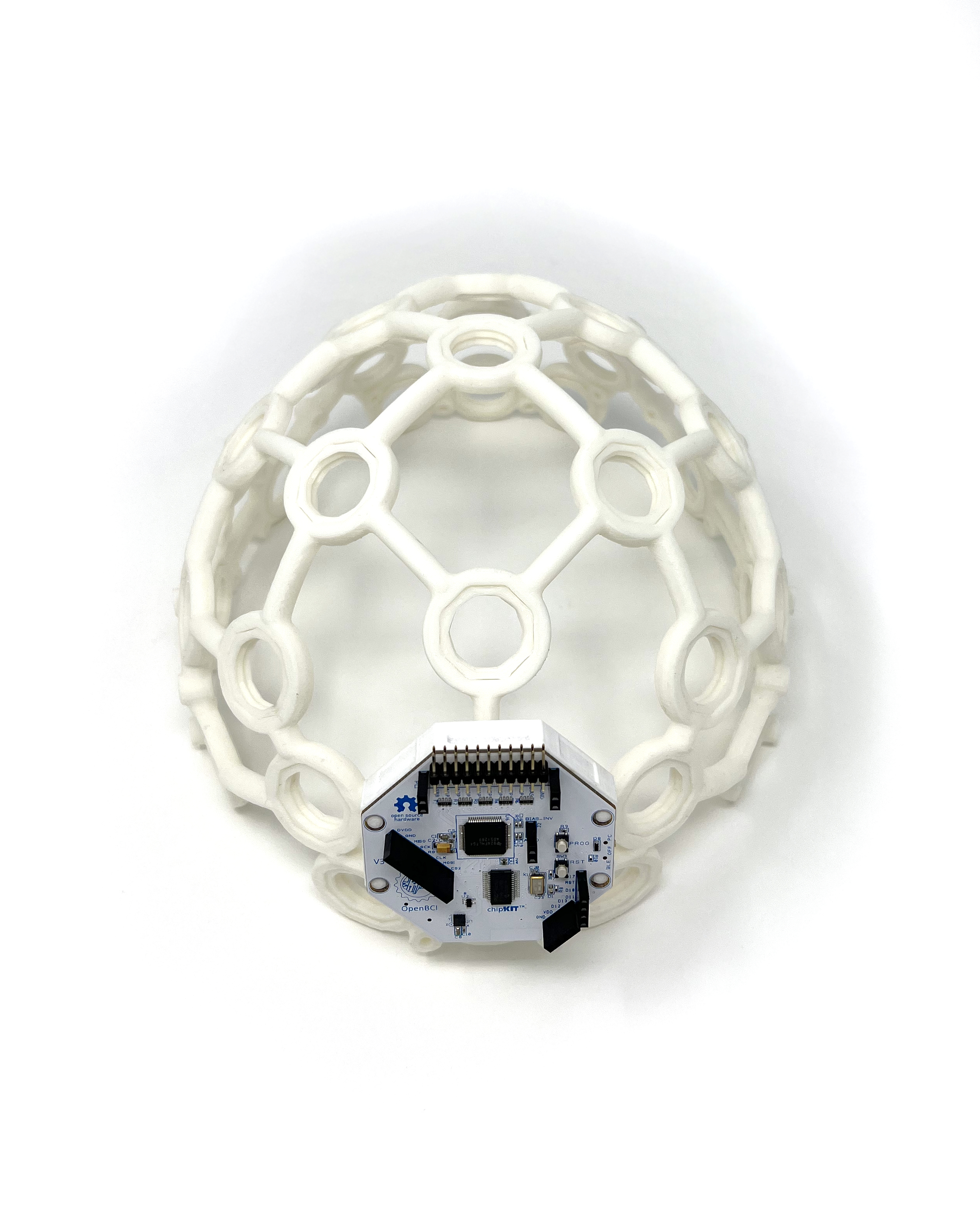
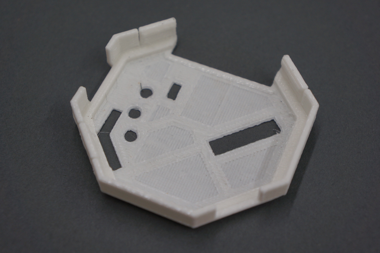
You can then secure the OpenBCI Board to the BOARD_MOUNT by clipping BOARD_COVER over top.
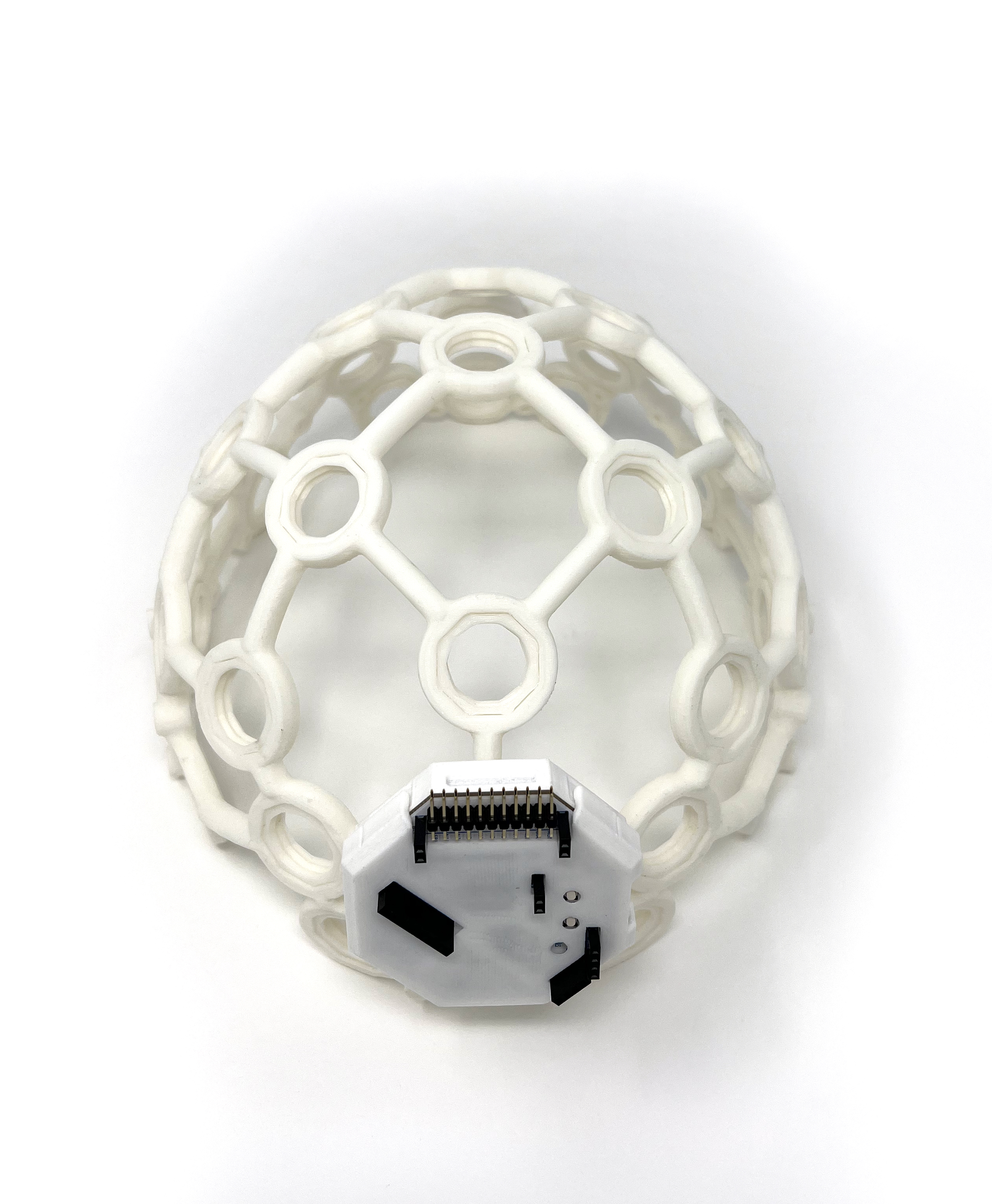
The pins and female headers should fit neatly into the BOARD_COVER holes as shown.
Electrode location overview
Before creating your electrode mounts, it's a good idea to think about where you may want to place the electrodes on the Ultracortex FRAME. The placement of the electrode may affect how long you make the wire between the electrode and where the OpenBCI is mounted, at the back of the frame.
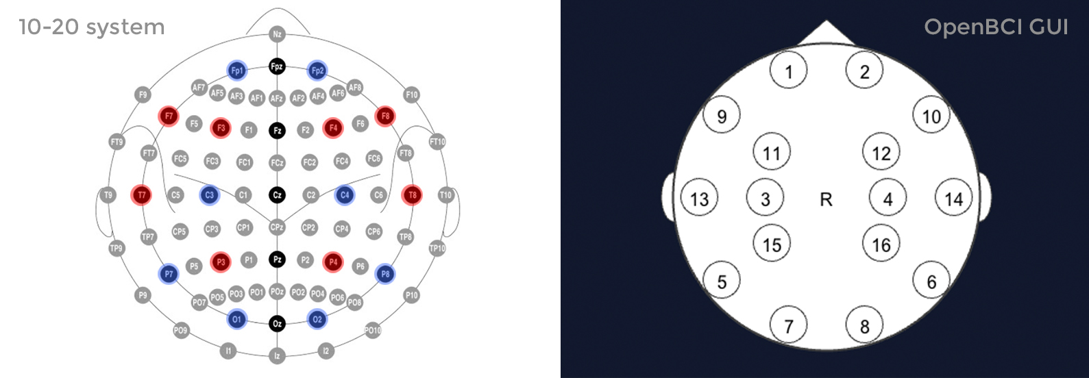
The Ultracortex node locations are based on the 10-20 system, which is the internationally accepted standard for electrode placement in the context of EEG.
The images below indicates the default 10-20 electrode locations that the OpenBCI Graphical User Interface expects. This application is great for viewing/recording your EEG and can be found in our OpenBCI_Processing repo. The blue nodes indicate the 8 default 10-20 locations (channels 1-8) of the Cyton Board. The red nodes indicate the default 10-20 locations of channels 9-16 when using the OpenBCI 16-channel R&D Kit.
For the remainder of this tutorial, the blue nodes on the 10-20 system diagram (channels 1-8 of the OpenBCI default settings) will be used. The channel to 10-20 system correlations are as follows:
- Channel 1(N1P) - Fp1
- Channel 2(N2P) - Fp2
- Channel 3(N3P) - C3
- Channel 4(N4P) - C4
- Channel 5(N5P) - P7
- Channel 6(N6P) - P8
- Channel 7(N7P) - O1
- Channel 8(N8P) - O2
Please open the image above in new tab to better recognize the position.
Placement of electrodes
First screw your two FLAT ELECTRODE UNITS in the front two nodes of the frame.
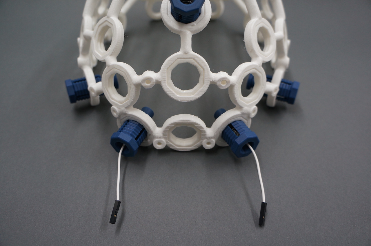
Then screw 6 SPIKEY ELECTRODE UNITS in the following nodes of the frame.
Connect wiring to OpenBCI
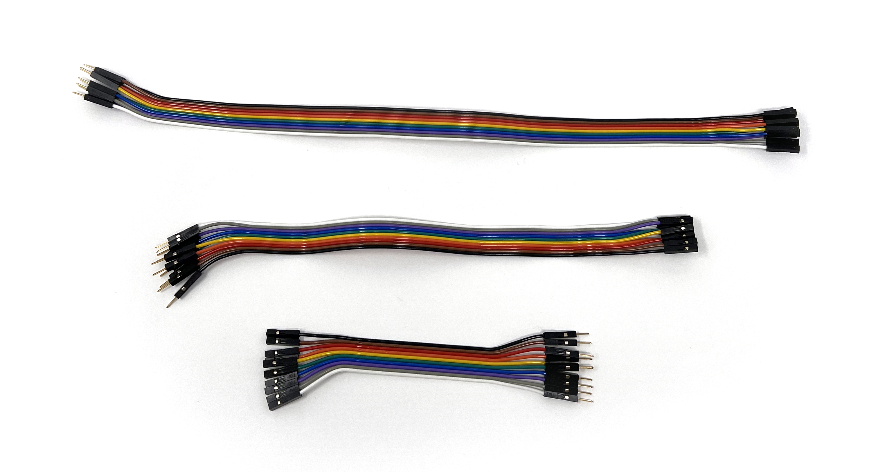
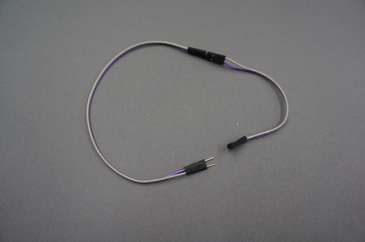
It's time to connect the electrodes to your OpenBCI Cyton board with jumper cables. You will find 3 ribbon cables in your kit as seen below.
Peel off the GRAY and PURPLE from the 12" set and the BLUE, GREEN, ORANGE and YELLOW from the 8" set and the RED and BROWN from the 4" set.
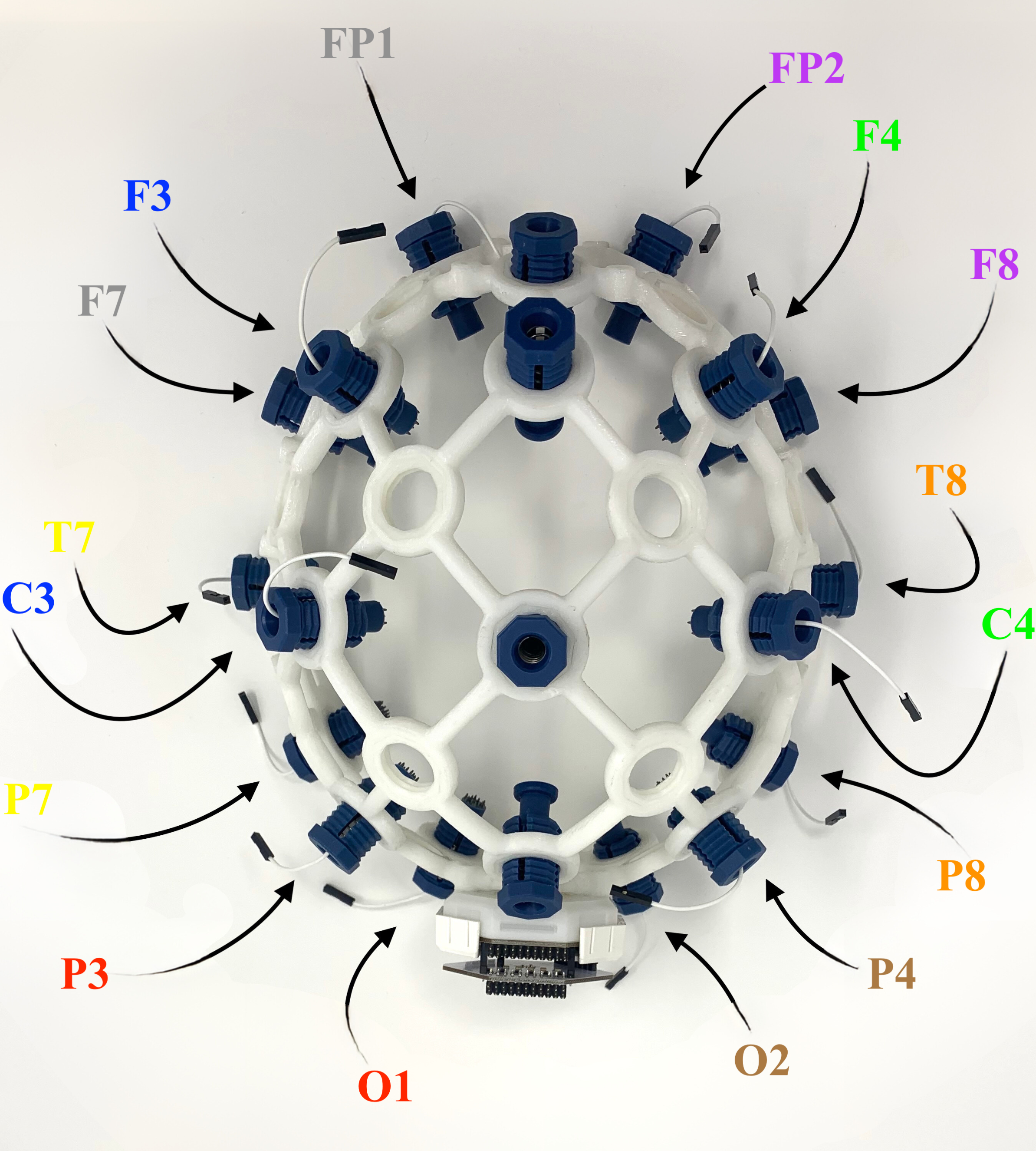
Now connect the jumper cables to the electrodes. The map below assigns names to all the electrodes by their location.
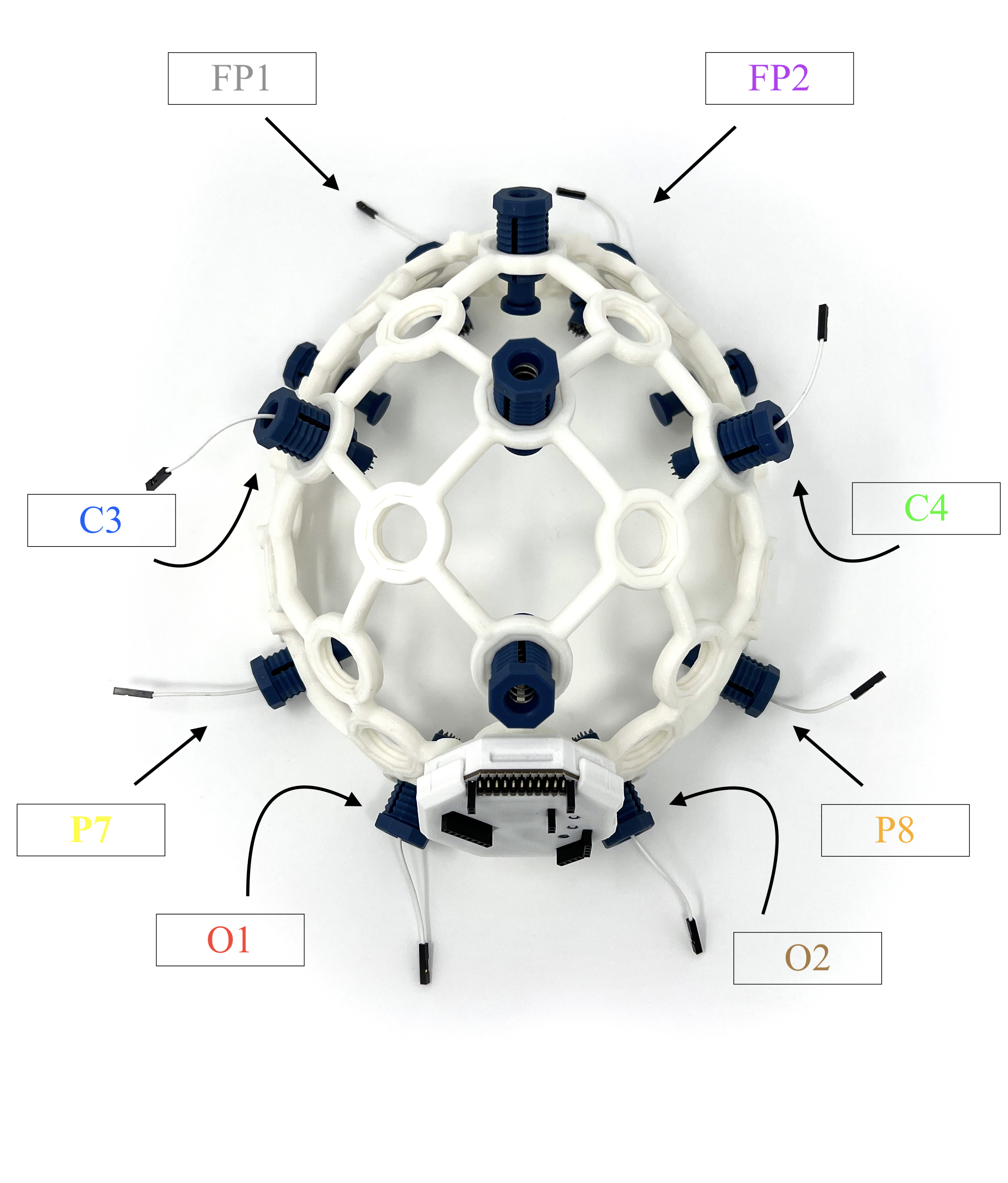
To follow along with this tutorial, attach each electrode to the corresponding wire color following the table and steps below. Here's a table with the correct electrode, wire color, and Cyton. By bottom pin, we mean the pin CLOSEST to the OpenBCI board.
| Electrode | Wire Color | Cyton Board Pin |
|---|---|---|
| Ear Clip | Black | Bottom SRB pin (SRB2) |
| FP1 | Grey | Bottom N1P pin |
| FP2 | Purple | Bottom N2P pin |
| C3 | Blue | Bottom N3P pin |
| C4 | Green | Bottom N4P pin |
| P7 | Yellow | Bottom N5P pin |
| P8 | Orange | Bottom N6P pin |
| O1 | Red | Bottom N7P pin |
| O2 | Brown | Bottom N8P pin |
| Ear Clip | Black | Bottom BIAS pin |
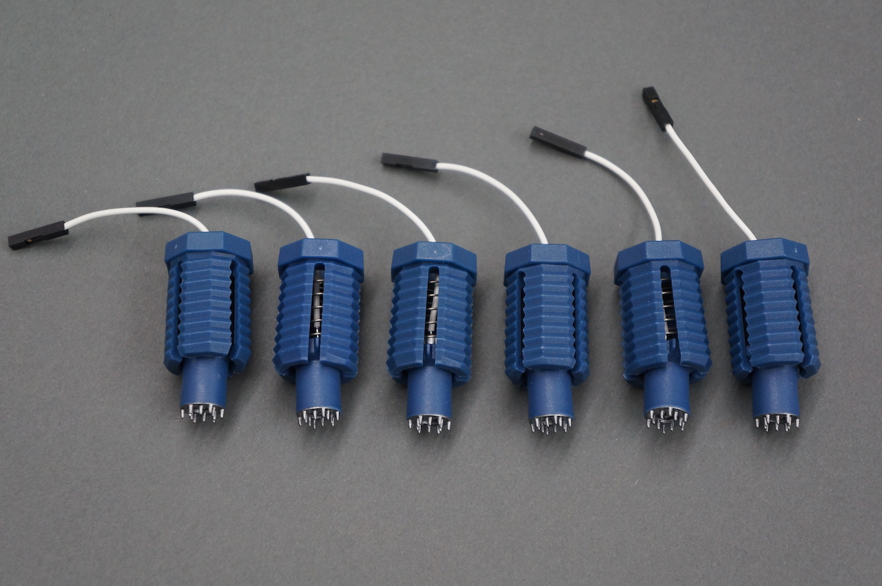
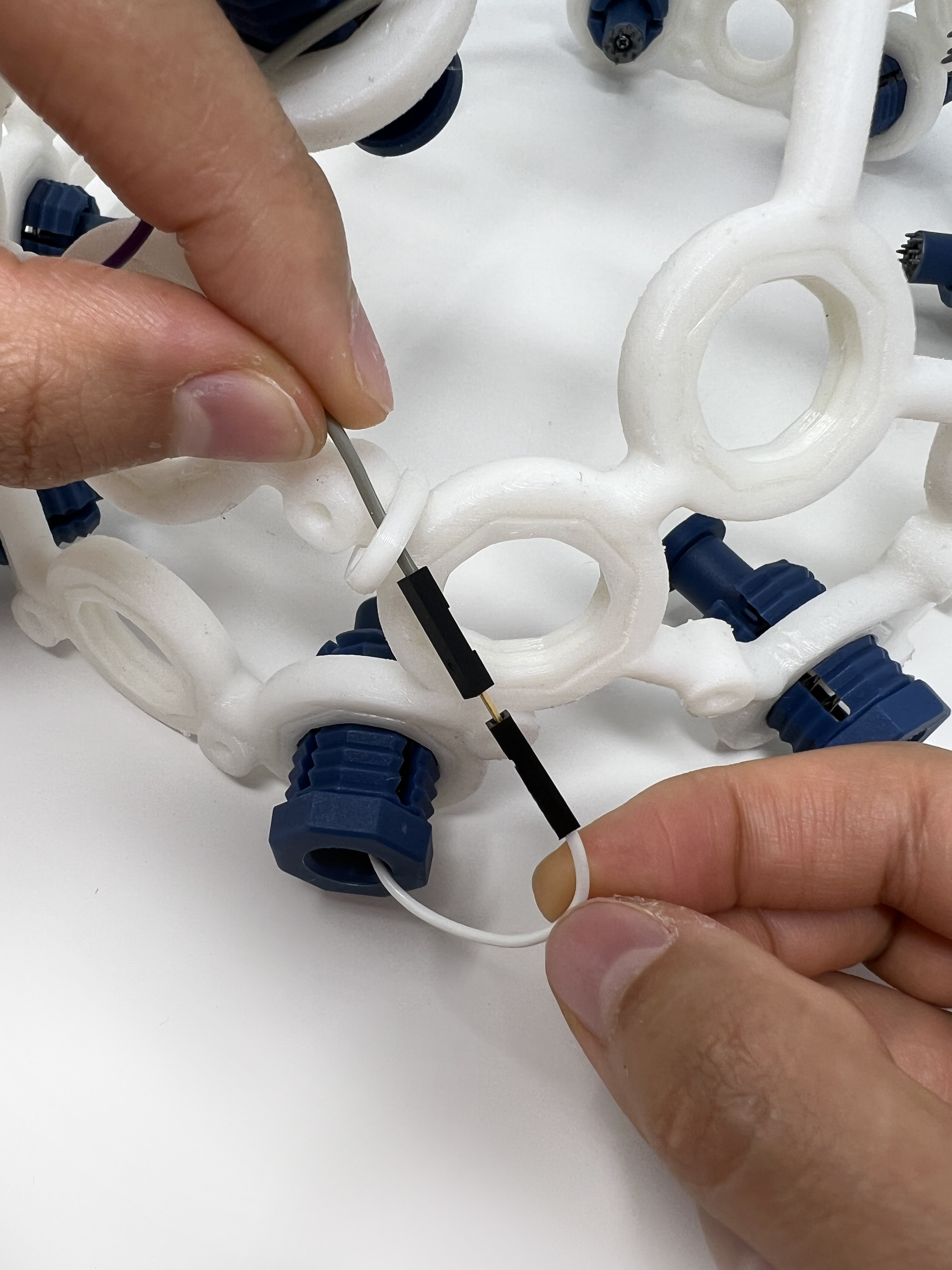
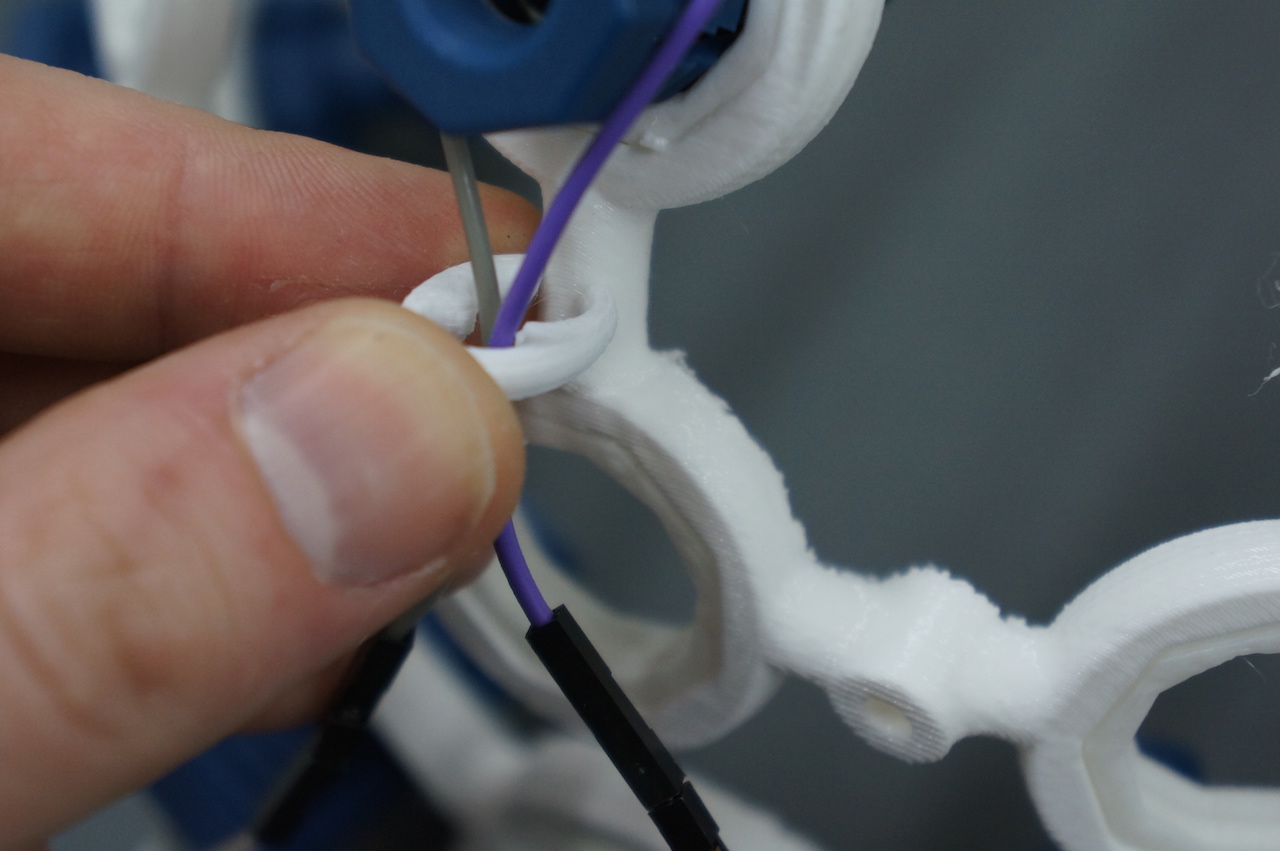
To connect wires to electrodes, plug the male end in to the header cable on the NODES as shown:
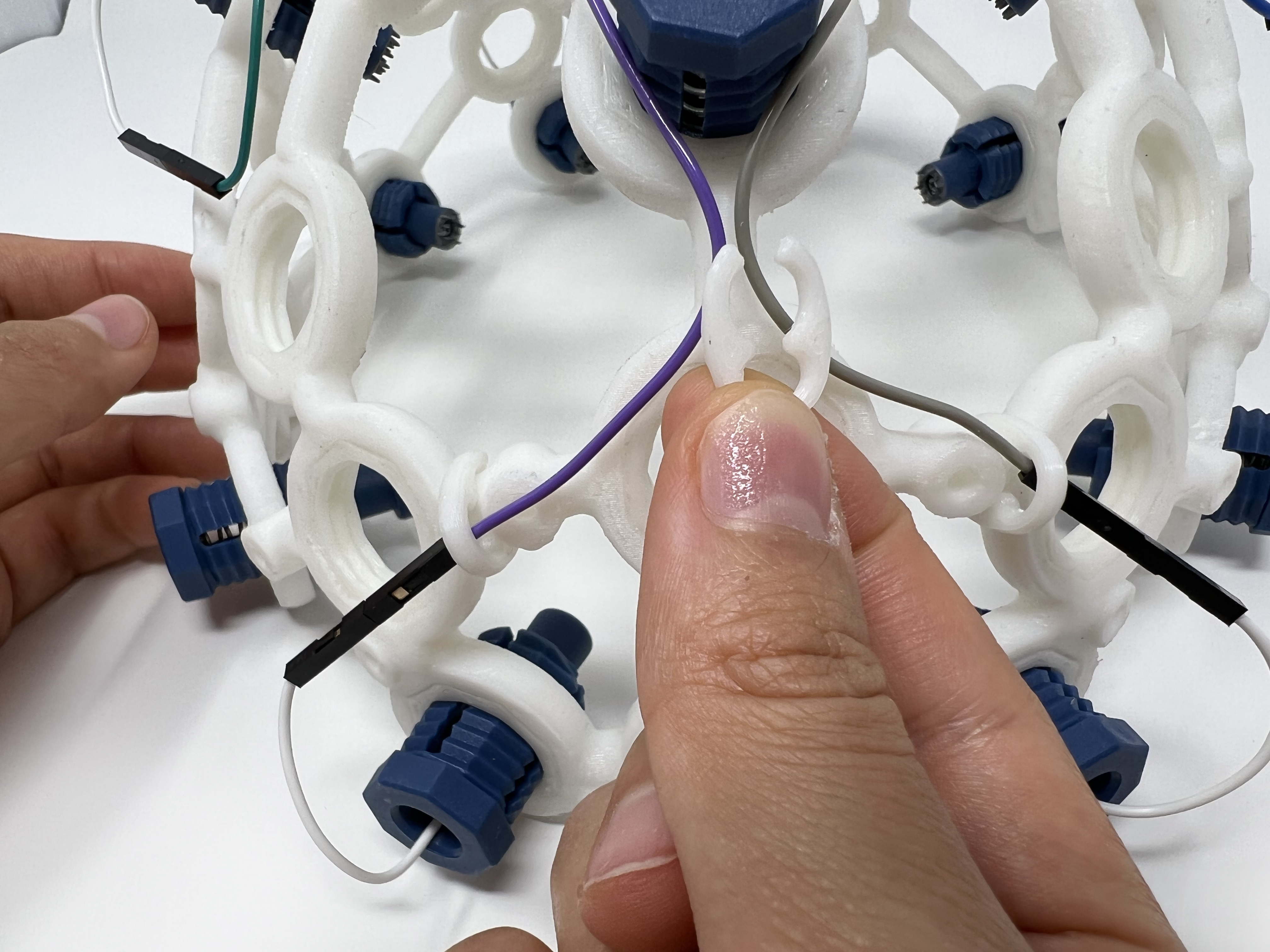
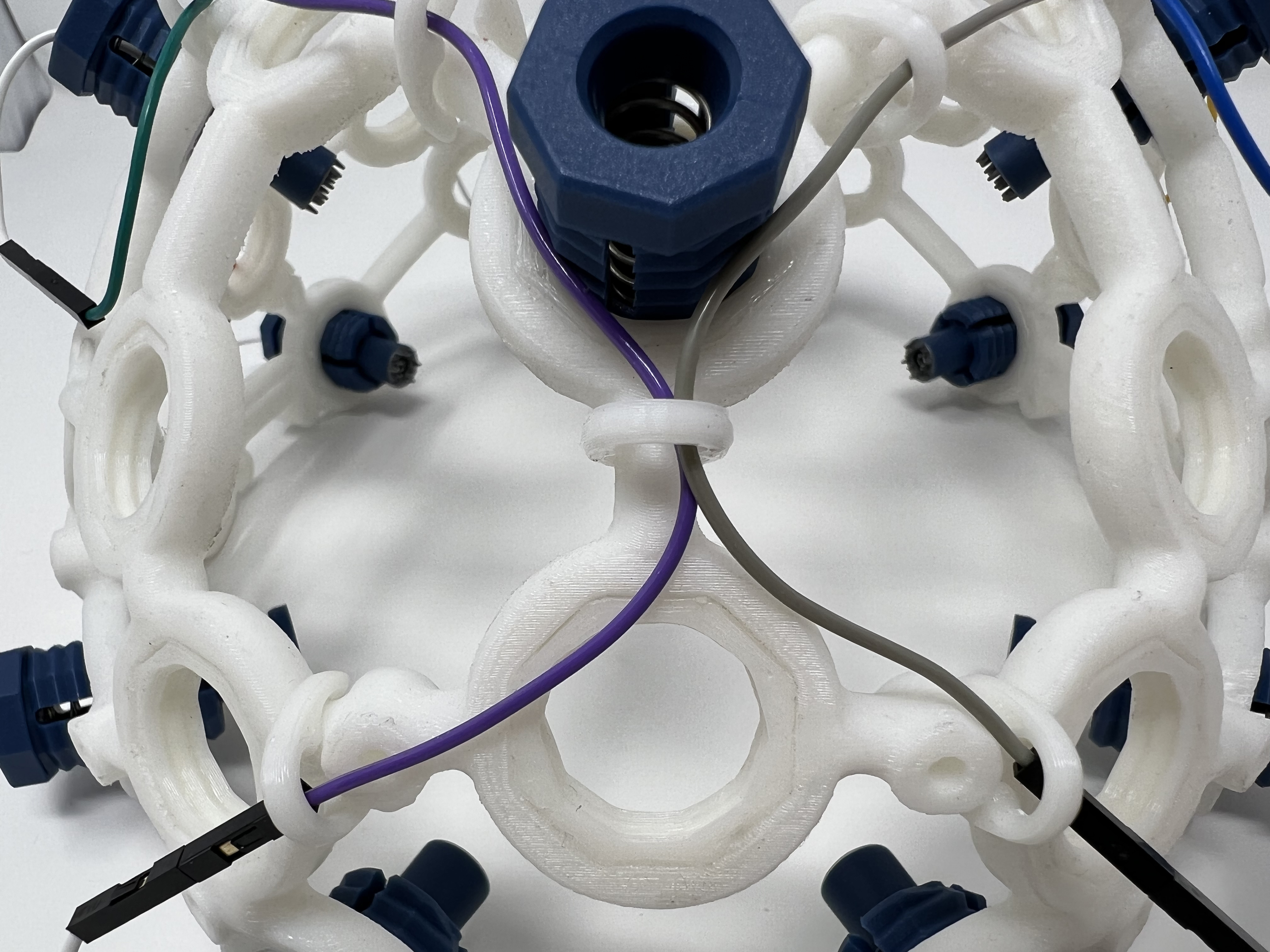
After connecting wires to electrodes, run wires along the frame to the top of the OpenBCI BOARD_MOUNT. Use the included plastic clips to hold wires on the frame, like shown:
Ear Clips
To use your Mark IV headset, you'll also need two ear clip electrodes, which come with your headset kit. These ear clip electrodes serve as the reference and bias (ground with common-mode noise rejection) for your EEG system. You will connect them to your OpenBCI board along with the electrodes in the next step.
Cyton Board Setup
Connect an OpenBCI Cyton board to the Mark IV as shown below:
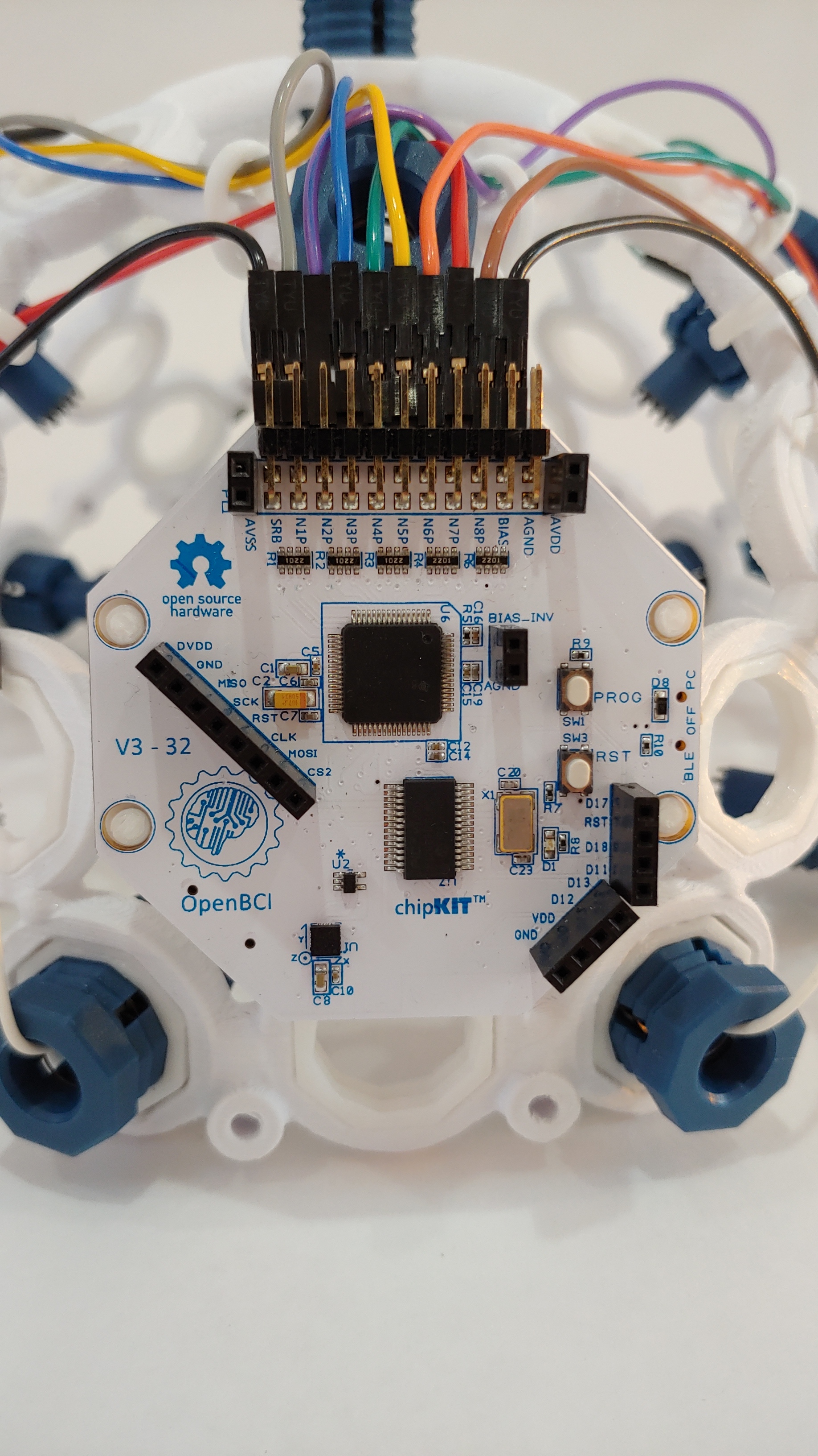
The electrodes (FP1 through O2) can be connected to any N1P, N2P, etc, channel. The ear clips must always be connected to the bottom SRB pin and either of the BIAS pins.
Replace the cover, as shown below:
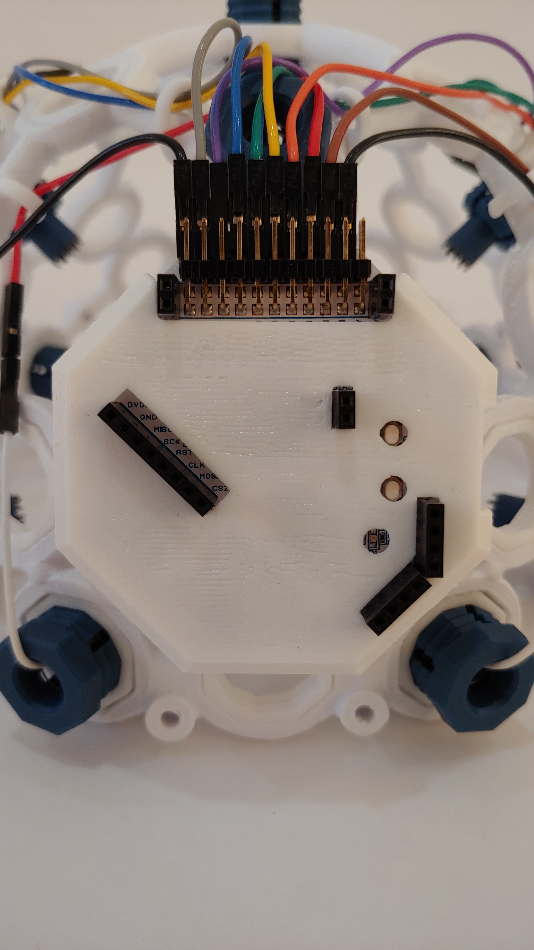
Your Cyton board is ready to use with your Mark IV headset!
Ganglion Board Setup
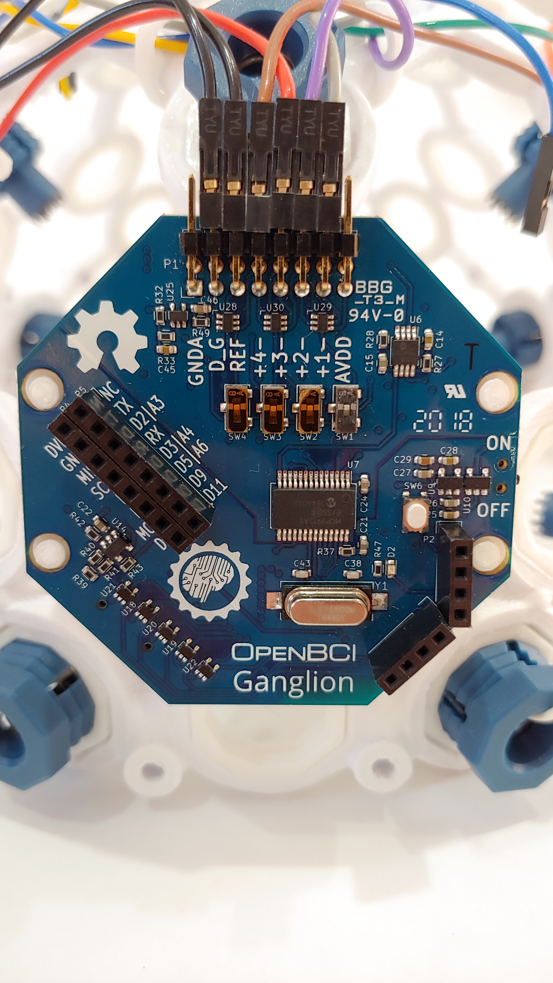
Connect an OpenBCI Ganglion board to the Mark IV as shown below (with cover removed for clarity). We placed 8 electrodes on our Mark IV headset, but the Ganglion board can only take 4 inputs. So, we can only connect 4 of our electrodes to the board - we chose FP1, FP2, O1, and O2 for this tutorial.
Here's a table with the correct electrode, wire color, and Ganglion board pin pairings:
| Electrode | Wire Color | Cyton Board Pin |
|---|---|---|
| FP1 | Grey | +4 (Top 4 pin) |
| FP2 | Purple | +3 (Top 3 pin) |
| O1 | Red | +1 (Top 1 pin) |
| O2 | Brown | +2 (Top 2 pin) |
| Ear Clip | Black | Top D_G pin |
| Ear Clip | Black | Top REF pin |
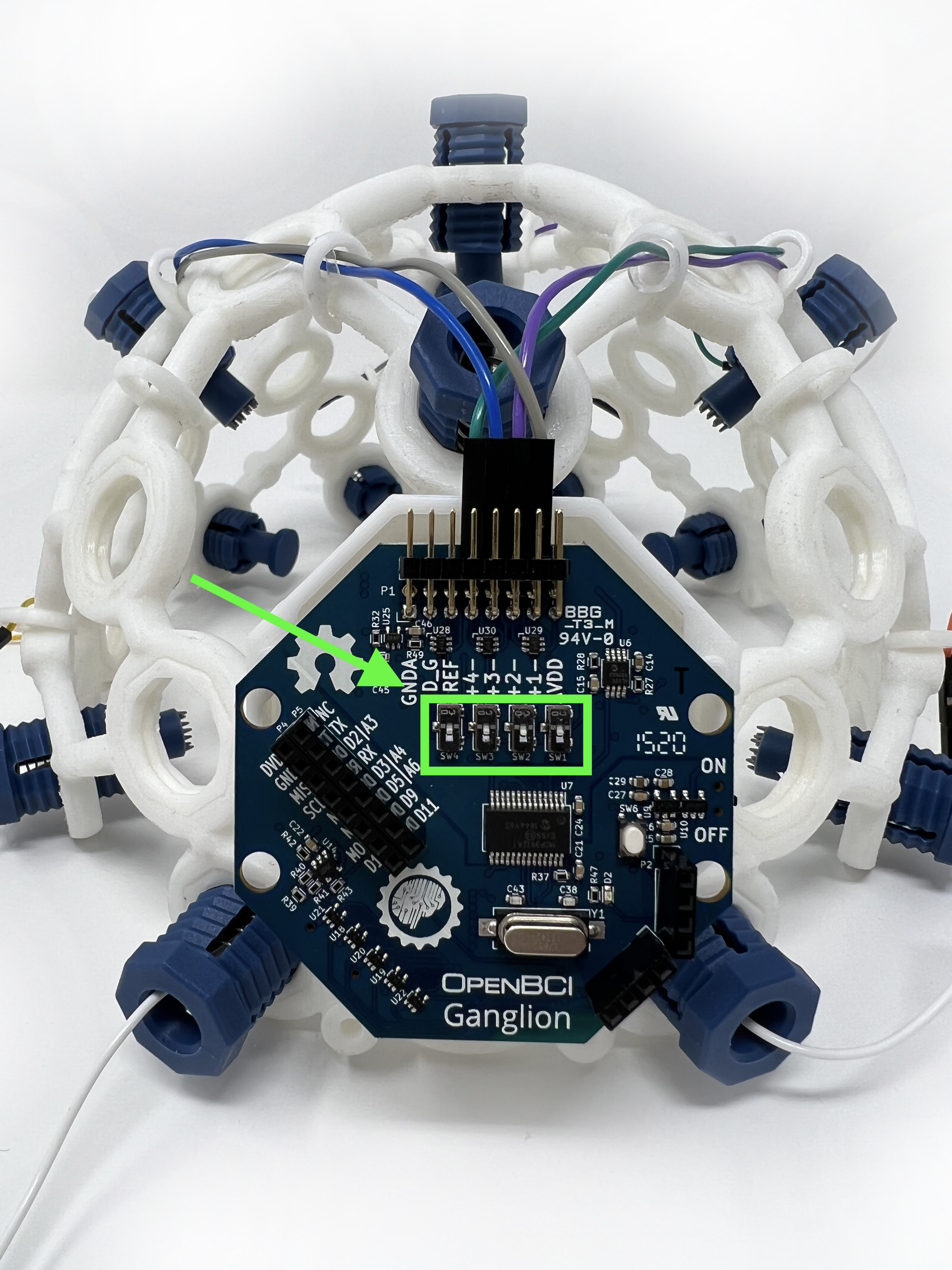
Next, make sure the switches on your Ganglion board are in the bottom configuration as shown below:
Replace the cover. Your Ganglion board is now ready to use with your Mark IV headset!
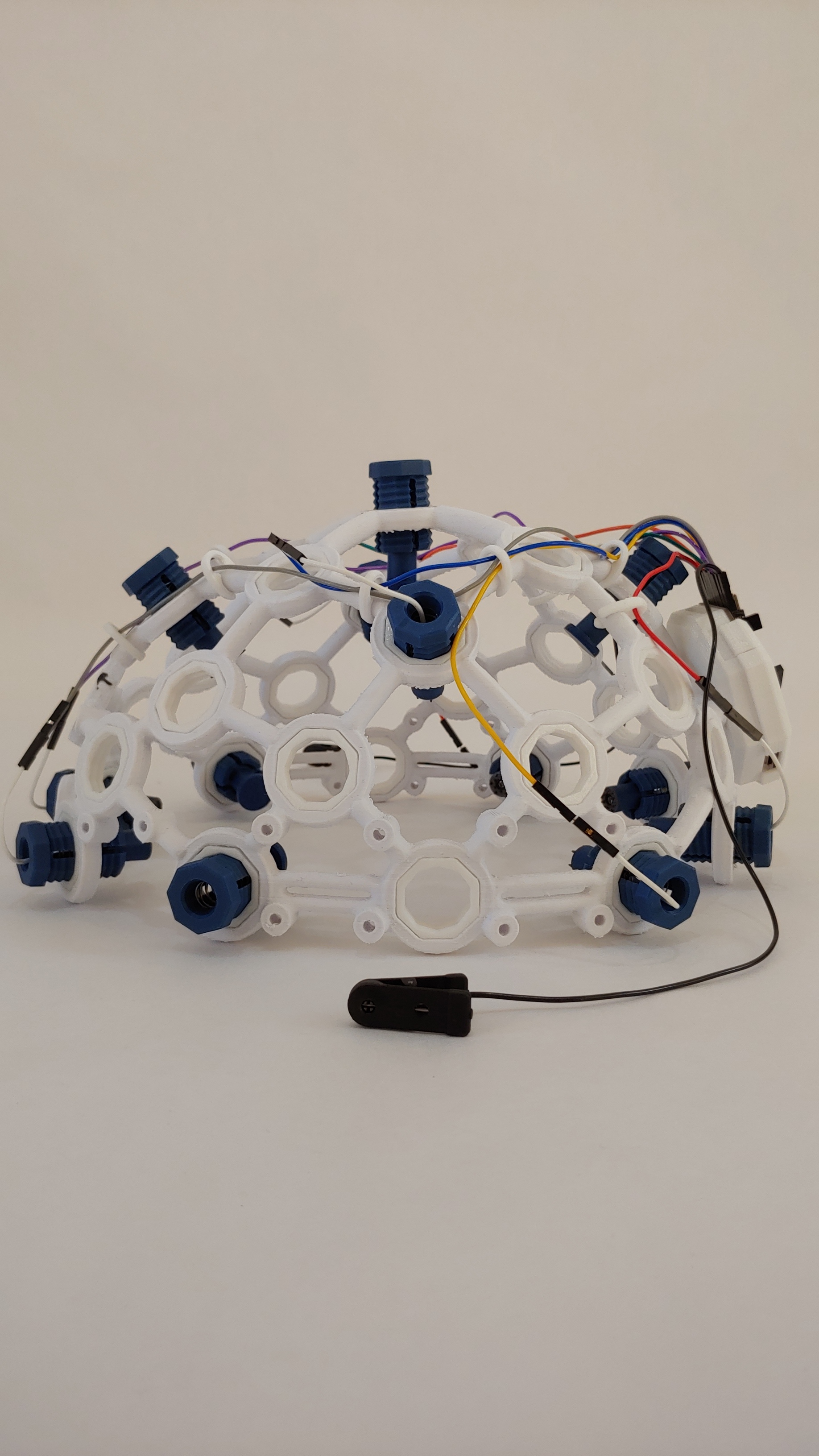
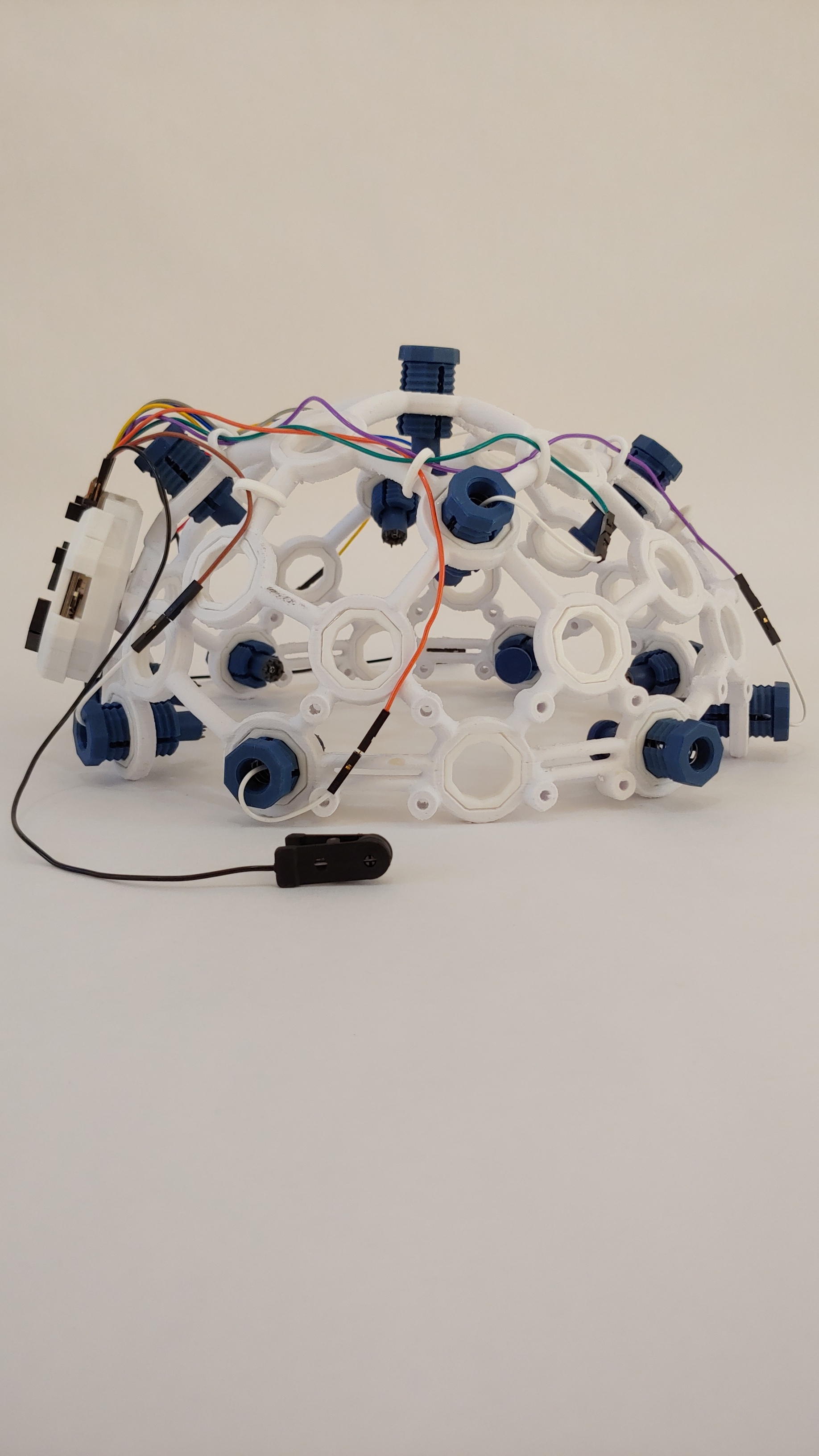
Completed 8 Channel Mark IV Setup
Your 8 channel headset is finished! To expand to a 16 channel headset (for use with Cyton Daisy), see the next section.
16 Channel Add-Ons
If you have a Cyton Daisy extension, you can expand your headset from 8 electrodes to 16 electrodes. Each electrode provides one "channel" of data, so we call this a 16 channel setup.
Adding extra electrodes
From the front of the frame remove the two Comfort Nodes and replace them with spiky electrodes. Add 6 more spiky electrode units in the locations shown below:
Wiring Electrodes
Take out your rest of your Ribbon Cables and separate the GRAY and PURPLE 8" & 4" cables, the BLUE, GREEN, ORANGE and YELLOW 8", and the RED & BROWN 8" cables. Plug the male end of the 8" GRAY and PURPLE to the 4" GRAY and PURPLE. These two extra-long wires will help you reach all the electrodes.
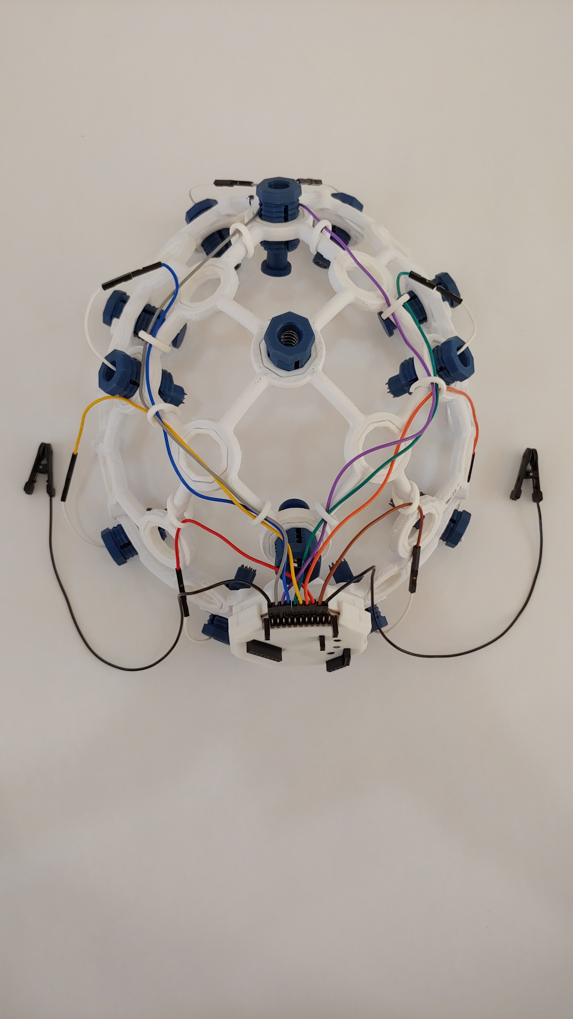
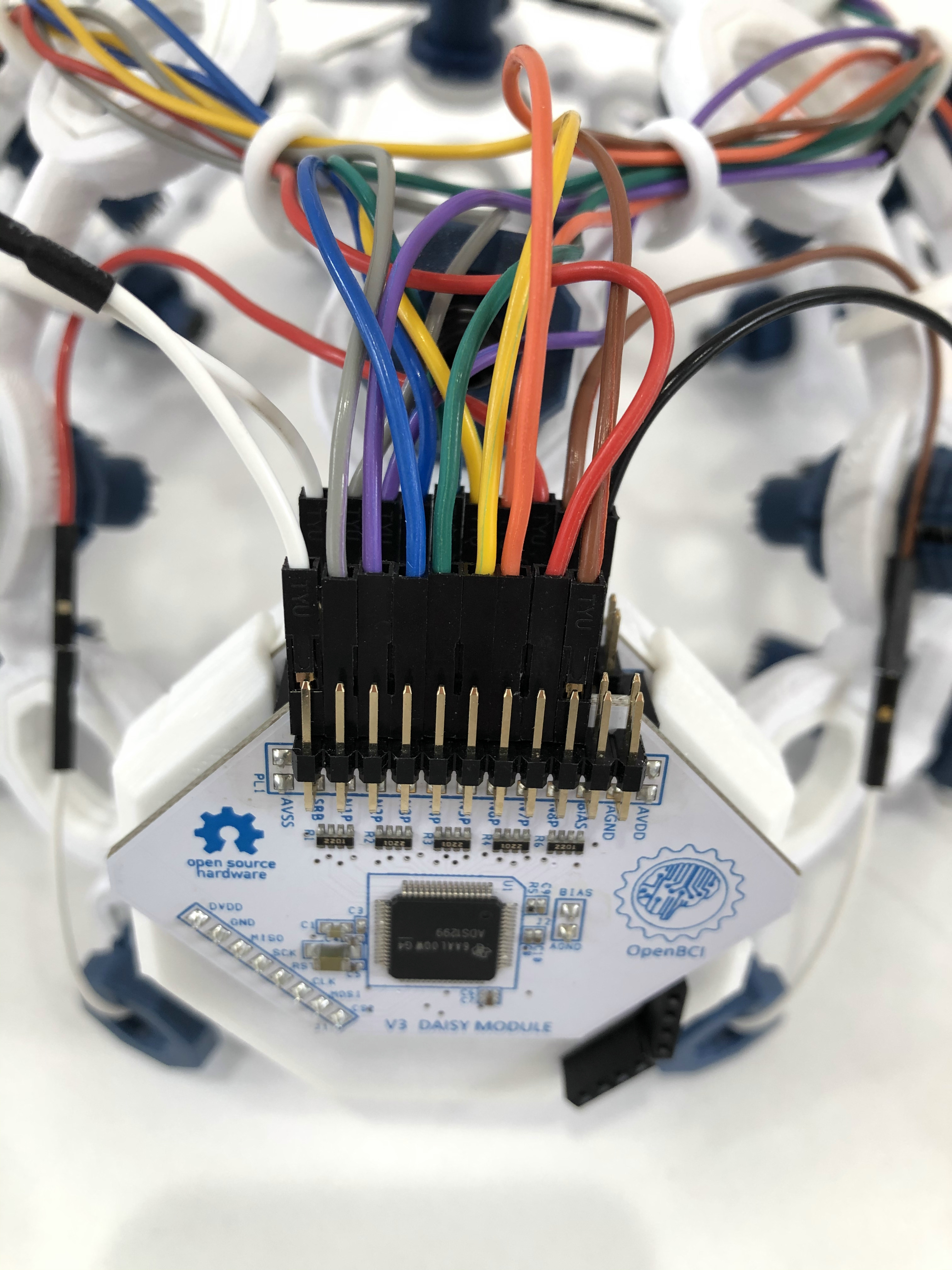
Next, connect one female end of the white Y-Splitter Cable to the bottom SRB pin of the Cyton. Connect the male end of the white Y-Splitter Cable to the female end of one black ear clip electrode. The other black ear clip electrode should be connected to the bottom BIAS pin of the Cyton. Bottom pins N1P through N8P of the Cyton should be connected to colored wires in the order shown below. Then, attach the Daisy extension to the outside of the Cyton board as shown below. You will plug all of the new electrodes into the Daisy board pins in the next step.
Connect each of the new electrodes to corresponding Daisy pins as shown below. You may have to use a different color scheme, depending on what wires you have available. Just make sure to keep track of which electrodes are connected to which Daisy pins.
The electrode and Daisy pin pairings are below:
| Electrode | Wire Color | Daisy Pin |
|---|---|---|
| F7 | Grey | Bottom N1P pin |
| F8 | Purple | Bottom N2P pin |
| F3 | Blue | Bottom N3P pin |
| F4 | Green | Bottom N4P pin |
| T7 | Yellow | Bottom N5P pin |
| T8 | Orange | Bottom N6P pin |
| P3 | Red | Bottom N7P pin |
| P4 | Brown | Bottom N8P pin |
The other female end of the white Y-Splitter Cable should be connected to the bottom SRB pin of the Daisy. The pins connected to the Daisy board should look like this:
Like for the first 8 electrodes, use the plastic clips to secure wires in place:
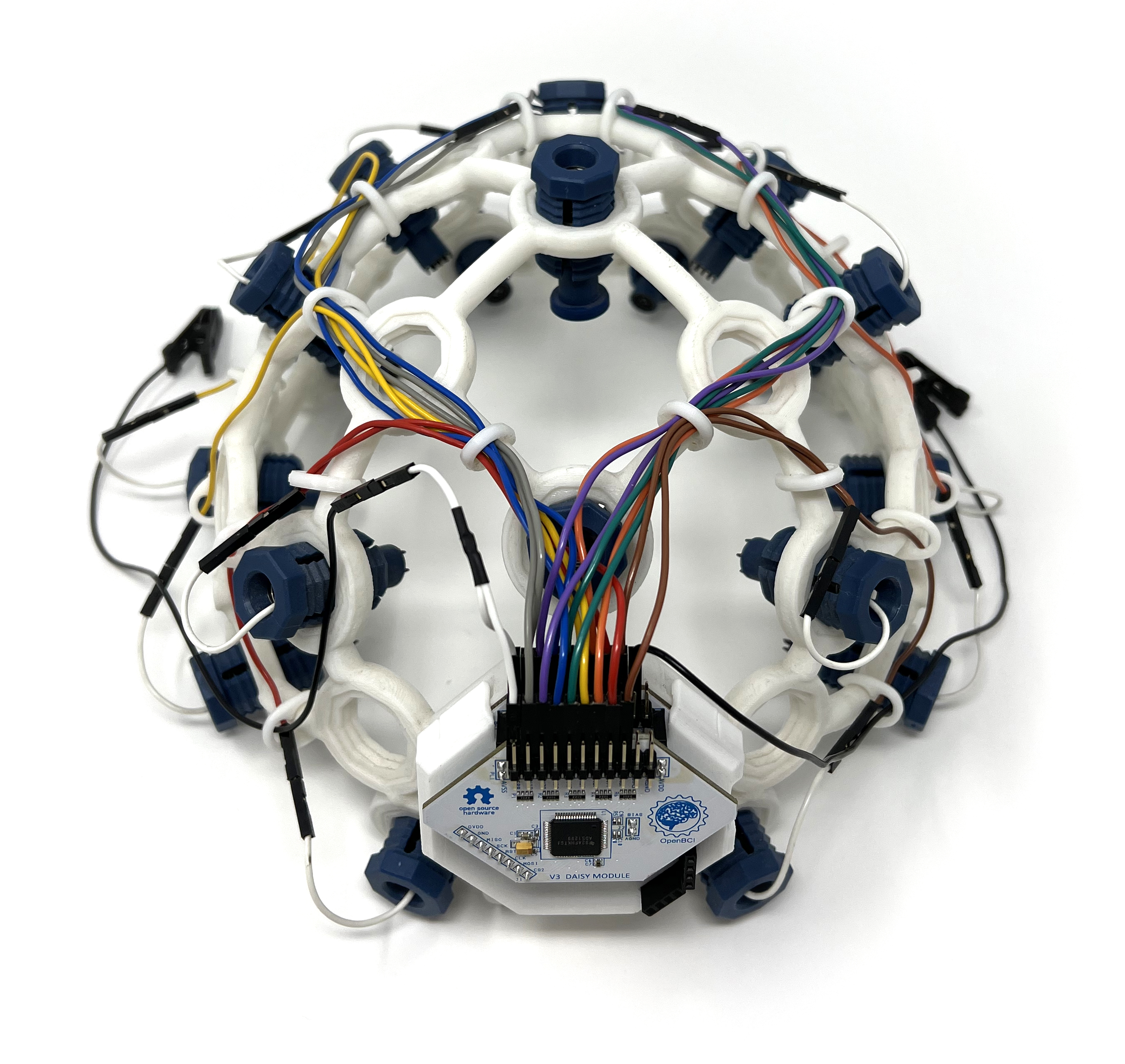
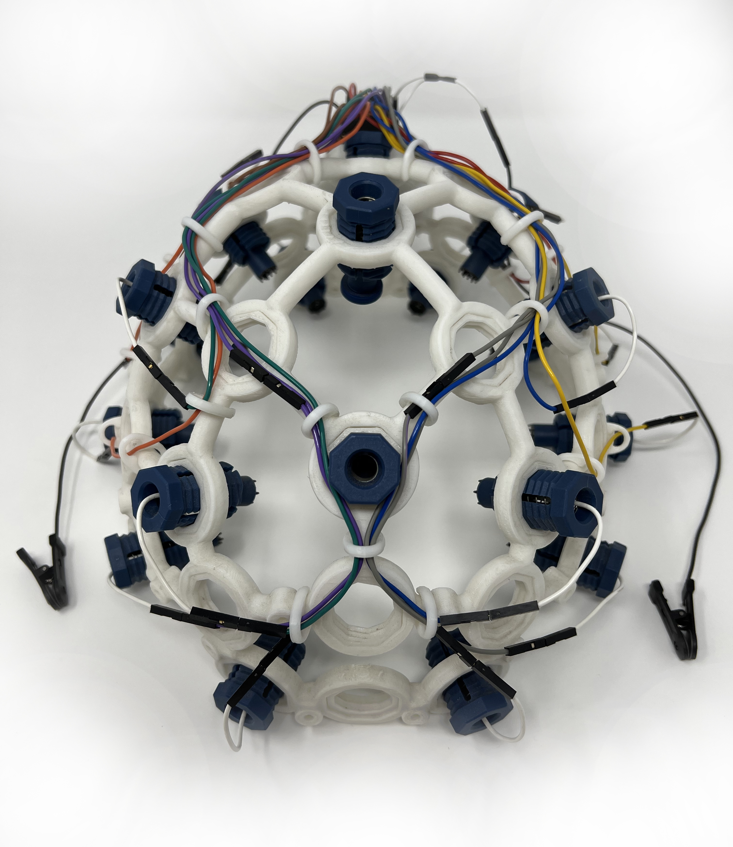
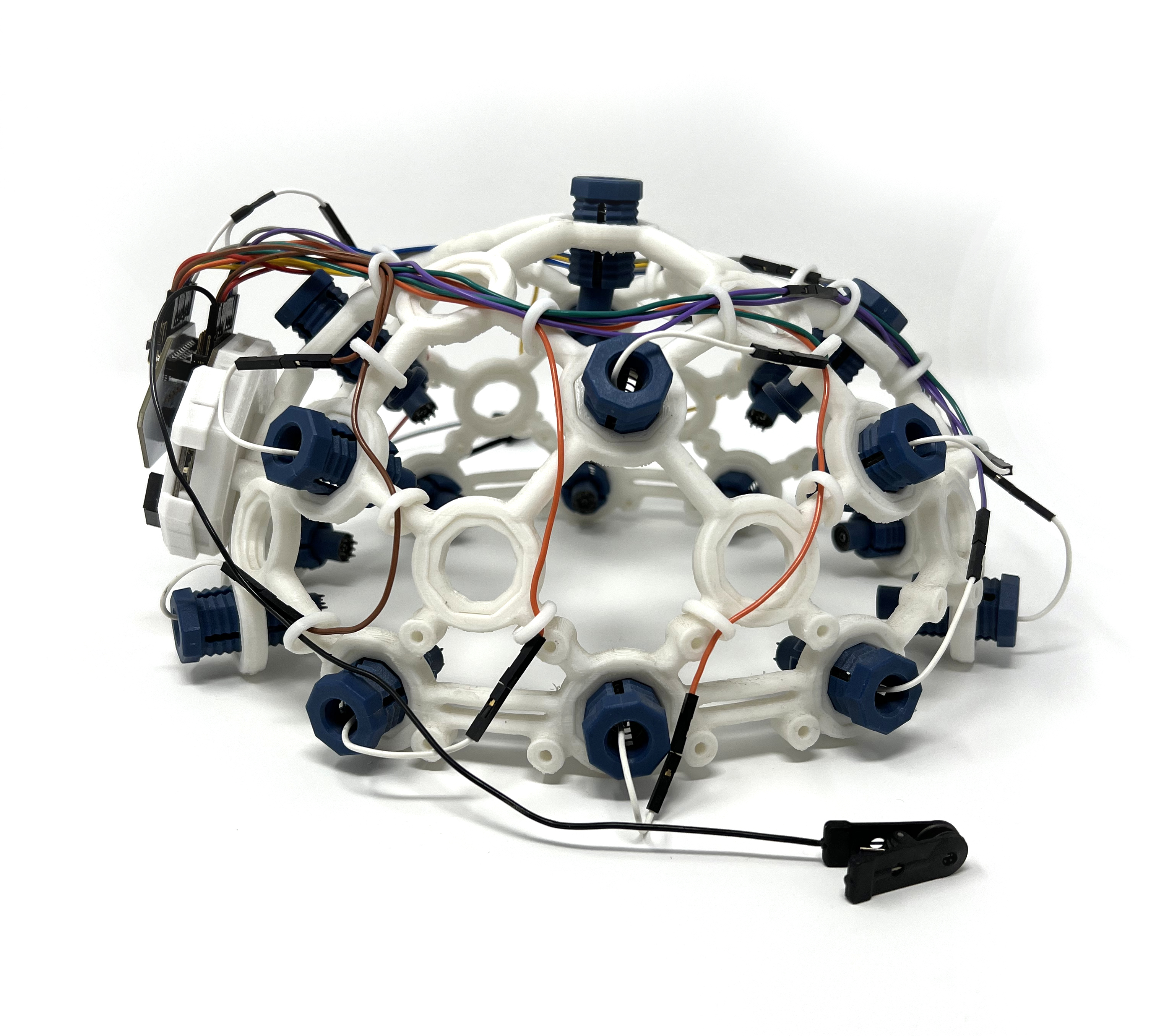
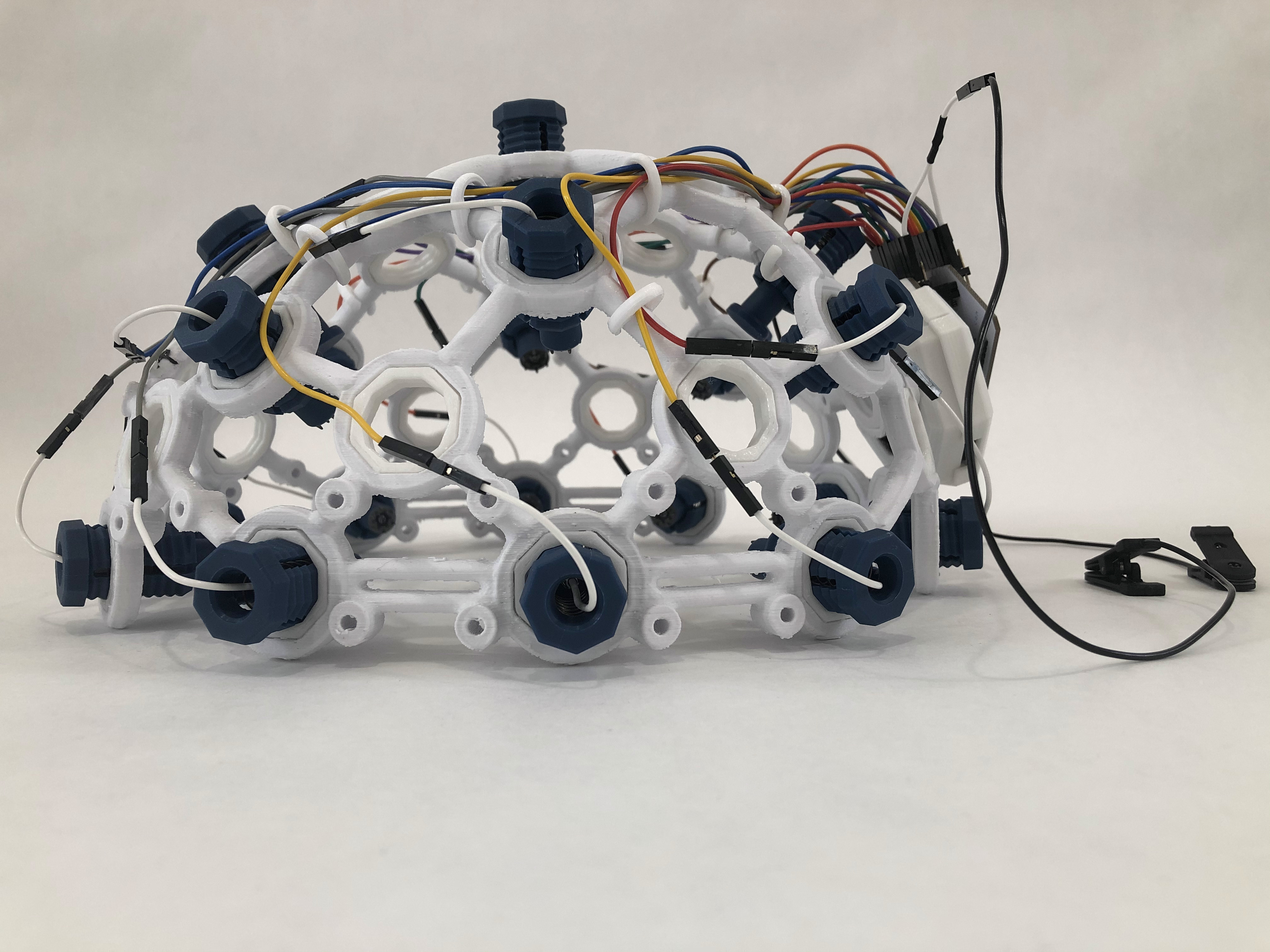
Your Mark IV is now ready to use 16 channels! It should look like the images below.
Adjust the Ultracortex for your head
Put the Ultracortex Mark IV onto your head and gradually tighten the electrode units until the electrodes are snugly (but comfortably) against your scalp. Tighten the electrodes and comfort units by turning them clockwise, and loosen them by turning counterclockwise.
Be careful not to strain the electrode wires when twisting the electrode units, or you may separate the wire from the electrode itself. You must disconnect a blue electrode mount from its colored wire before turning it.
Examine your brain waves!
Place your Ultracortex on your head so that the back center node is roughly the same distance above your inion (bump on the back of your skull) as the front center node is above the bridge of your nose. As you place the Ultracortex on your head, the springs should adjust to the shape and size of your head.
Now that you have your Ultracortex assembled and comfortably adjusted to your head size and shape, it's brain wave time!
Check out the Getting Started w/ OpenBCI tutorial to get up-and-running with the OpenBCI GUI.
Below is a screenshot of what the GUI looks like when you've got your OpenBCI Cyton + Ultracortex (w/ 8 channels) hooked up! You can see a nice alpha (~10 hz) spike on the FFT Plot.
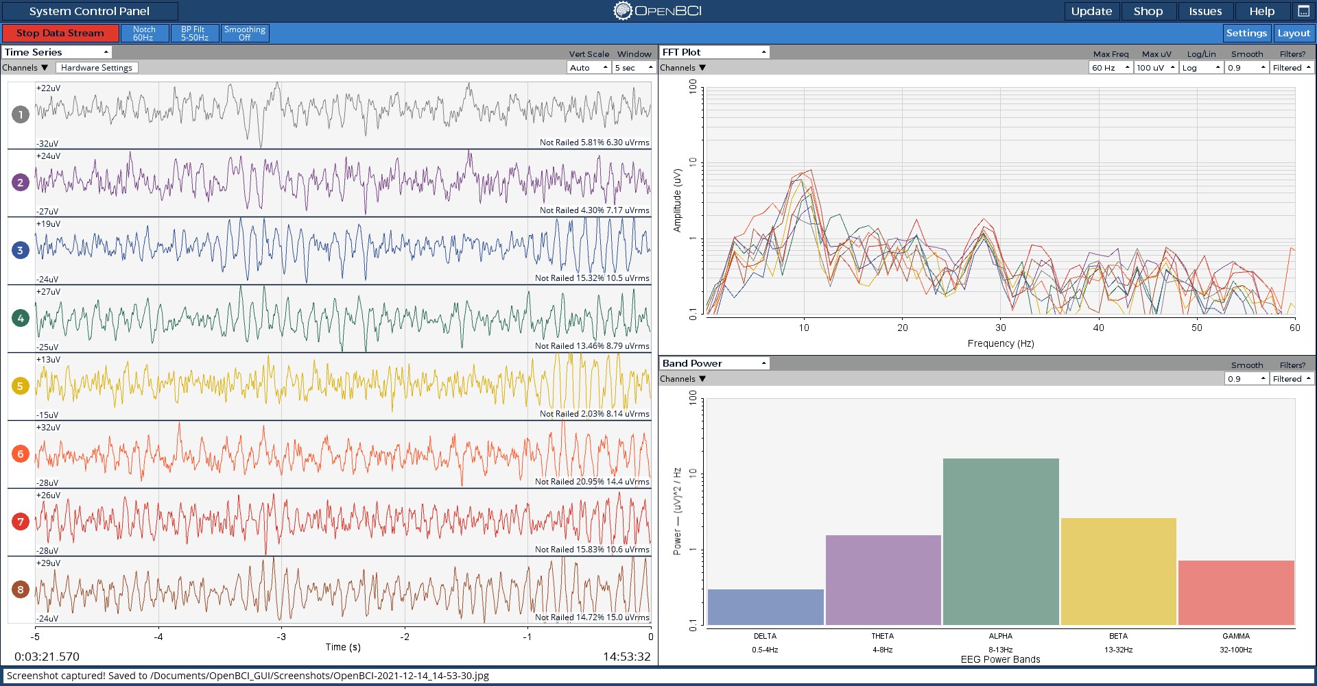
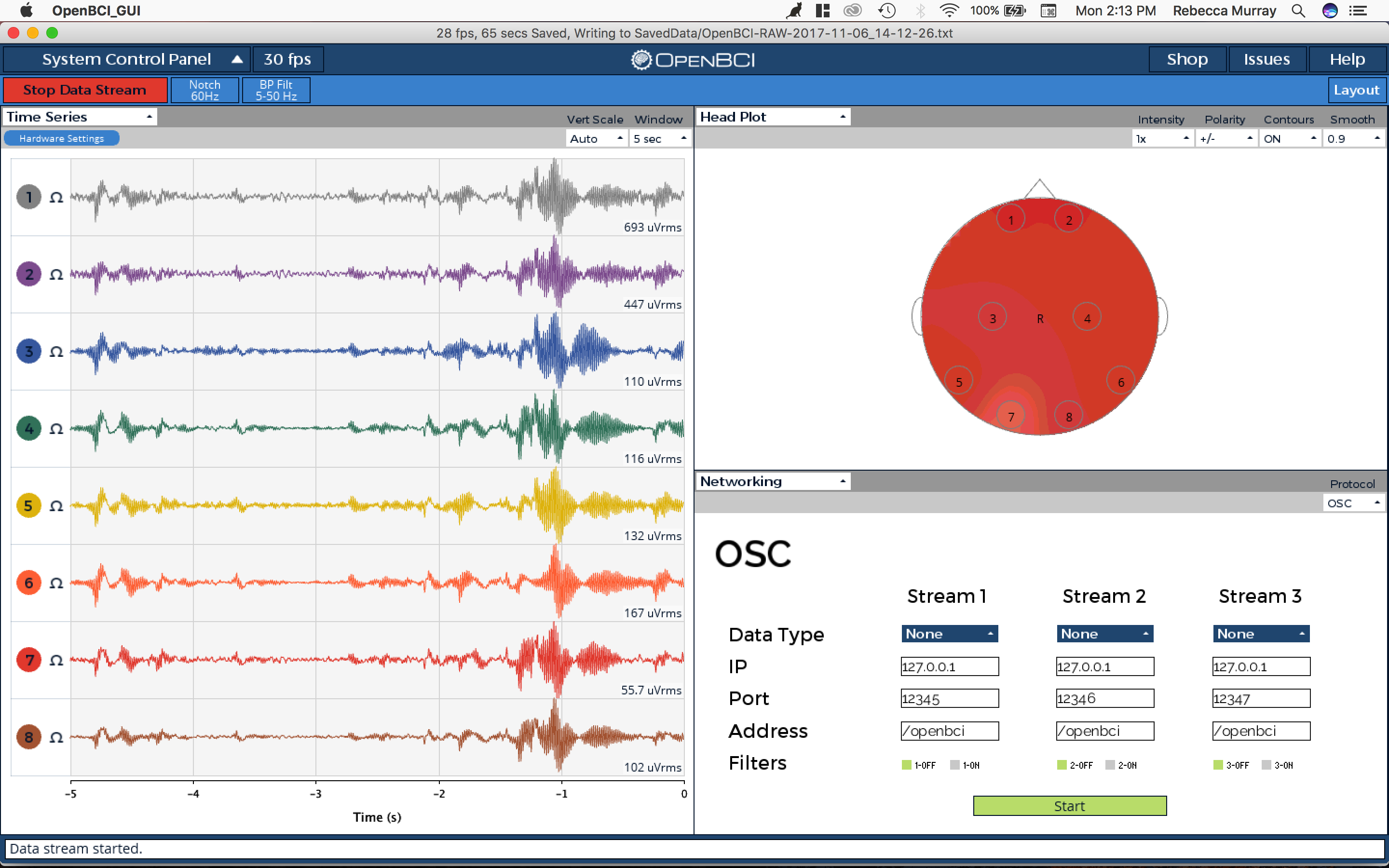
The OpenBCI GUI has a widget for visualizing signal strength at each electrode. To view it, click on the "FFT Plot" drop-down menu in the top right corner. Select "Head Plot".

You should now see a visual map of signal strength in the top right corner.
Give Us Feedback!
If you have questions, comments, or suggestions regarding the printing and/or assembly of the Ultracortex, we'd love to hear from you. Please submit issues to this repository or email us at contact@openbci.com. Or take some pictures of yourself wearing the Ultracortex and Tweet at us (@OpenBCI & @Ultracortex)!