Cyton Getting Started Guide
This guide will walk you through setting up your computer to use the Cyton and USB Dongle, using the OpenBCI_GUI Application, and how to get EEG/EMG/EKG from your own body! Please review this guide in its entirety before starting and consult the Cyton Biosensing Tutorial Video for extra guidance. Have fun!
I. What You Need
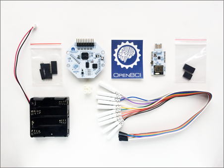
- OpenBCI Cyton Board
- OpenBCI Dongle
- Electrodes and cables, such as OpenBCI Gold Cup Electrodes and Ten20 Paste
- Lithium battery and charger OR 6V battery pack (AA batteries not included)
- Board Case
1. Your Board
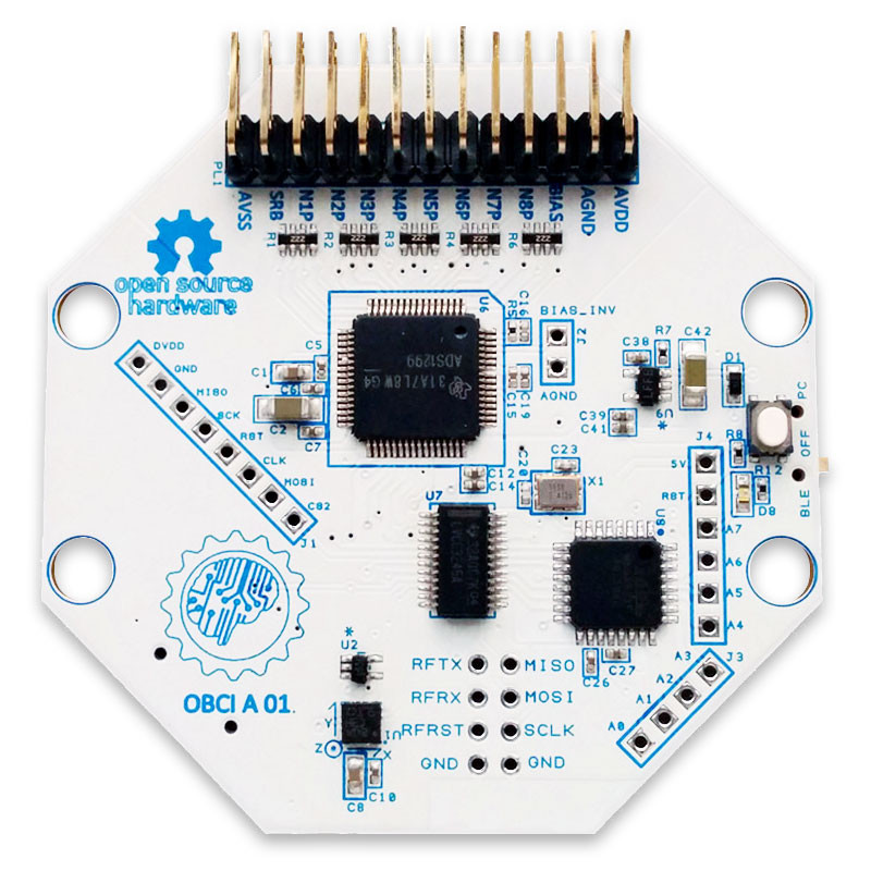
This tutorial can be followed if you are working with any Cyton board (8-bit, Cyton, or Cyton with Daisy). I'll be working with the 8-bit board.
2. Your OpenBCI USB Dongle
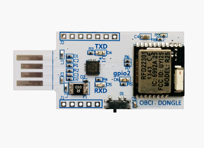
The OpenBCI USB Dongle has an integrated RFDuino that communicates with the RFDuino on the Cyton board. The dongle establishes a serial connection with your computer's on-board FTDI chip. The serial port is called /dev/tty* (if you're using Linux or Mac) or COM* (if you're using Windows). You'll be connecting to this serial port from the OpenBCI GUI or whatever other software you want to end up using to interface your Cyton board.
3. OpenBCI Gold Cup Electrodes and Electrode Paste
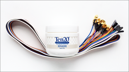
If you ordered an OpenBCI Gold Cup Electrodes and Ten20 Paste you should have:
- 10 passive, gold cup electrodes on a color-coded ribbon cable
- A jar of Ten20 conductive electrode paste
If you plan to work with your own electrodes, the touch-proof adapter may come in handy:
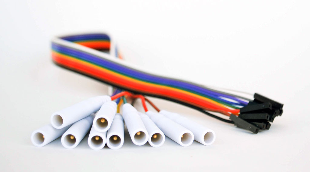
It will convert any electrode that terminates in the industry-standard touch-proof design to an electrode that can be plugged into any OpenBCI Board!
For best results, when plugging female header pins onto the OpenBCI board, orient the sides with the 'silver latch bit' face-up since that side is a tiny bit wider than 0.1".
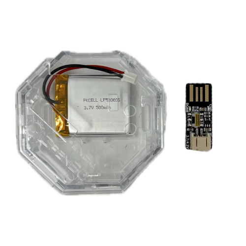
4. Your Lithium Polymer Battery and USB Charger (or 6V Battery Pack & 4 AA Batteries, pre-2023)
Fully charge the Lithium Polymer Battery, until the charger's indicator LED turns green. To do this, insert the battery's white plug into the matching slot on the USB charger (shown on the right), and connect the charger into a USB port.
Pre-2023:
Cyton boards have specific input voltage ranges. These input voltage ranges can be found on the back-side of the board, next to the power supply. BE VERY CAREFUL to not supply your board with voltages above these ranges, or else you will damage your board's power supply. For this reason, we recommend that you always use the battery pack that came with your OpenBCI kit.
Important note If you are using a non-OpenBCI battery holder (not recommended), please check the polarity (red +/black -) BEFORE powering up your OpenBCI board. A reversed polarity will burn out your board.
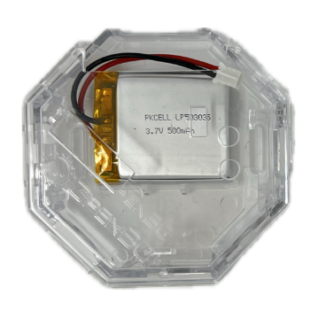
5. Clear Board Case
Recommended: use the clear case that comes with your board.
II. Download/Install/Run the OpenBCI GUI
Please follow the step by step guide to install the OpenBCI_GUI as a standalone application. Keep an eye out for specific Cyton requirements such as installing the FTDI VCP driver.
Come back to this guide when your GUI is running!
III. Prepare your OpenBCI Hardware
1. Plug in your OpenBCI USB Dongle
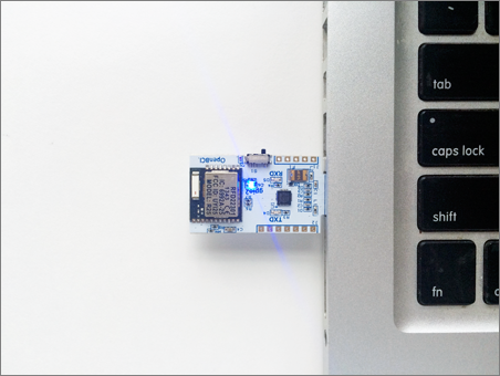
Plug this in (facing upwards!) and you should see a blue LED light up and stay on, as well as a red LED blink.
Note: make sure your USB Dongle is switched to GPIO 6 and not RESET. The switch should be set closer to your computer as seen in the picture to the right.
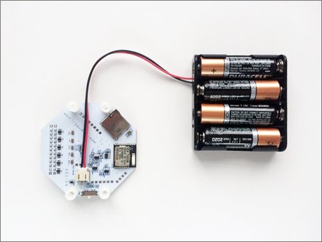
2. Plug in your Lithium Polymer Battery (or 6V AA battery pack (with batteries)
Cyton boards have specific input voltage ranges. These input voltage ranges can be found on the back-side of the board, next to the power supply. BE VERY CAREFUL to not supply your board with voltages above these ranges, or else you will damage your board's power supply. For this reason, we recommend that you always use the battery pack that came with your OpenBCI kit. There's a good reason we put this notice in here twice!
3. Switch your Cyton board to PC (not OFF or BLE)
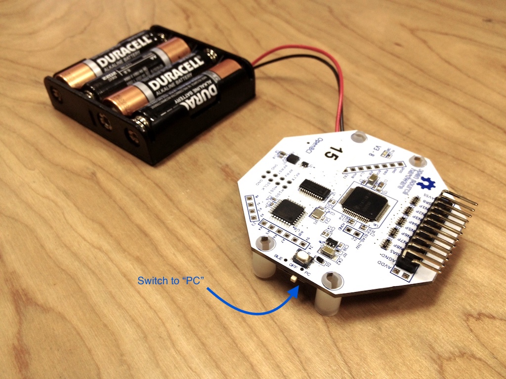
Make sure to move the small switch on the right side of the board from "OFF" to "PC". As soon as you do, you should see a blue LED turn on. If you don't, press the reset (RST) button just to the left of the switch. If the LED still does not turn on, make sure you have full battery. If you're sure your batteries are fully charged, consult the hardware section of our Forum.
Note: it's important to plug in your Dongle before you turn on your Cyton board. Sometimes, if the data stream seems broken, you may need to unplug your USB Dongle and power down your Cyton board. Make sure to plug your USB Dongle in first, then power up your board afterwards.
IV. Connect to your Cyton board from the GUI
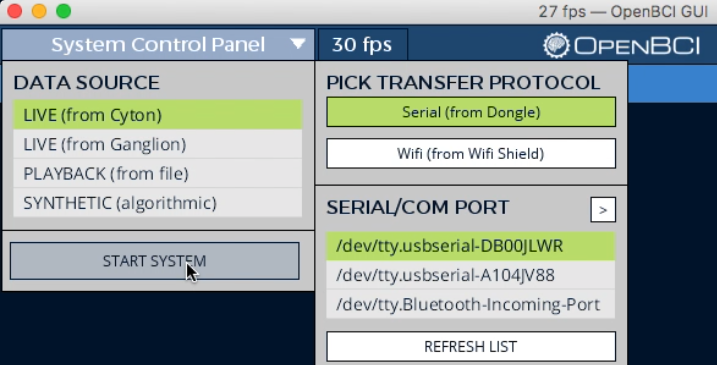
1. Select LIVE (from Cyton)
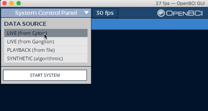
In order to connect to your Cyton, you must specify the data source to be LIVE (from Cyton) in the first section of the System Control Panel. Before hitting the START SYSTEM button, you need to configure your Cyton board (follow the steps below).
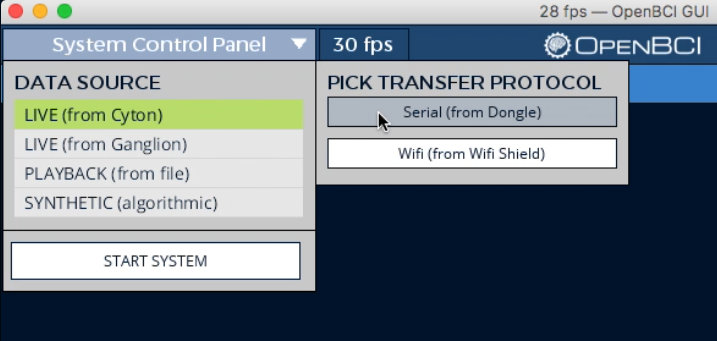
2. Select Serial Transfer Protocol
Next select Serial (from Dongle).
3. Find your USB Dongle's Serial/COM port
In the first section of the LIVE (from Cyton) sub-panel, find your Dongle's Serial/COM port name. If you're using a Mac or Linux, its name will be in the following format:
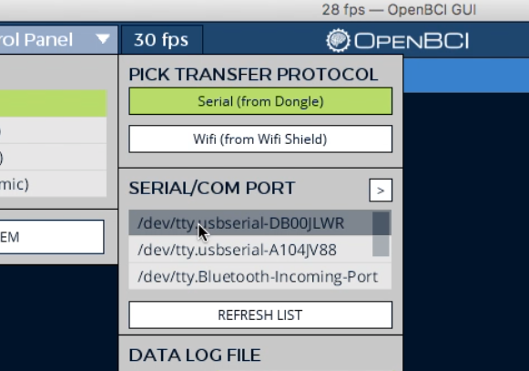
/dev/tty*
If you're using Windows, it will appear as:
COM#
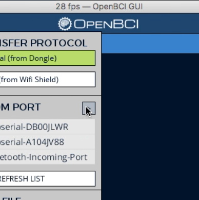
Your USB Dongle's port name will likely be at the top of the list. If you don't see it:
- Make sure your dongle is plugged in and switched to GPIO 6 (not RESET)
- Click the REFRESH LIST button in the SERIAL/COM PORT section of the sub-panel
If you're still having trouble finding your USB Dongle's port name, refer to the Forum for help debugging your hardware connection.
4. Select your channel count (8 or 16)

The CHANNEL COUNT setting is defaulted to 8. If you are working with an OpenBCI Daisy Module and Cyton board (16-channel) system, be sure to click the 16 CHANNELS button before starting your system.
5. Optional Settings
If you're comfortable using the GUI, use the optional settings in this dropdown section. Otherwise, skip to step 6!
Check Status or Change Radio Channel
There is a Radio Configuration tab that you can use to check the status of your Cyton system and change the radio channel. Click on the > arrow to open up the options panel. Here you will find tools for configuring your Cyton Radio connection. Let's walk through the functions of each button.
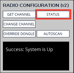
Click on the STATUS button to check the status of your Cyton system. This may take a few seconds to report, as it reaches out to your Dongle and Cyton board to verify that they are talking to each other. If they are, you will see the message Success: System is Up. If not, you will see Failure: System is Down.
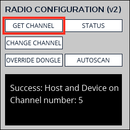
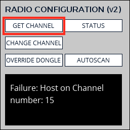
Click the GET CHANNEL button to know the channel that your Cyton system is communicating on. If the system is up, you will get the message Success: Host and Device on Channel number: X. If the system is down, you will get the message Failure: Host on Channel number: X.
NOTE: The Host radio is on the Dongle, and the Device radio is on the Cyton board.
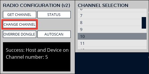
Click on the CHANGE CHANNEL button to change the channel that your Cyton system is communicating on. This can be really useful if you have multiple Cyton systems in the same space. When you click the button, a menu will open up with the channels. When you click on the channel you want, it will take just a second, and you should get the message Success: Host and Device on Channel number: X.
IMPORTANT: Make sure that there are no other Cyton boards active in the immediate area when you change the channel!
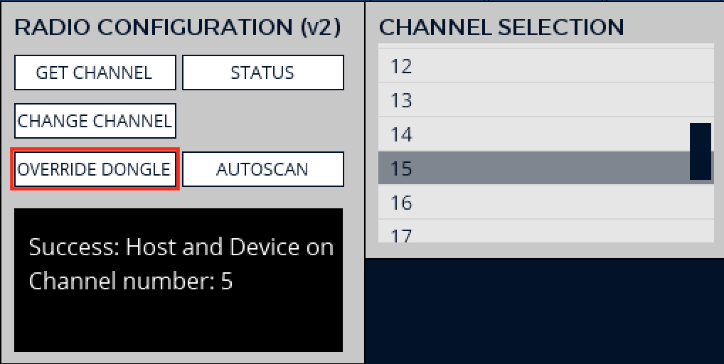
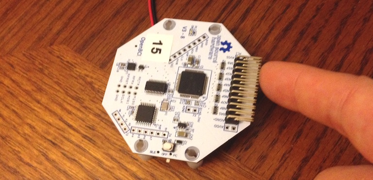
Click on the OVERRIDE DONGLE button to change the channel of the OpenBCI Dongle only. When you click the button, a menu will open up with the channels. For the purpose of this Tutorial, go ahead and change the Dongle channel to Channel 15. When you click on the channel number, it will take just a second, and you should get the message Success: Host override - Channel number: 15
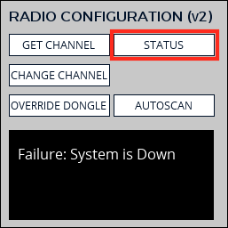
Since you have just changed the channel of the Dongle only, When you click on the STATUS button, you will get a failure message. Similarly, when you press the GET CHANNEL button you will also get a failure message. But don't worry! We can use the Autoscan function to get your Cyton Board and Dongle back on the same track!
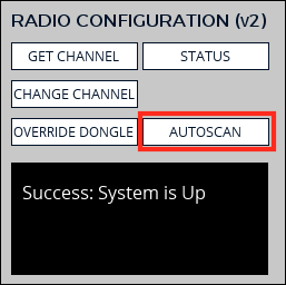
Now, click the AUTOSCAN button. It may take a few seconds for the Dongle to scan through every channel until it connects to your Cyton, but it will, and you will get the message Success: System is Up Autoscan!
Edit the Playback file name

In the DATA LOG FIlE section of the LIVE (from Cyton) sub-panel you can specify the name of your playback file. This file name is automatically defaulted to:
\Documents\OpenBCI_GUI\OpenBCI-RAW- + date/time
You can edit the name of this file by clicking in the "File Name" text field.
Playback files and user data are stored in /Documents/OpenBCI_GUI/ on all OS. OpenBCI Playback Files use CSV formatting and plain text.
After creating a Playback file, it can be replayed by running Playback File data source mode. As a result, you can easily share recorded OpenBCI Playback files with your friends and colleagues.
Select your SD setting
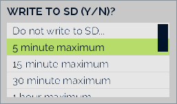
If you want to log data to a MicroSD inserted into the Cyton Board, in the WRITE TO SD (Y/N)? sub-panel section you can select the maximum recording time of the file. This setting is defaulted to "Do not write to SD…" and will automatically switch to this if you do not have a MicroSD card properly inserted into your Cyton board.
Note: Be sure to select a file size that is larger than your planned recording time. The Cyton writes to the local SD in a way that enables us to write lots of data very quickly. As a result, however, we must specify how large the file will be before we begin. The technique is known as block writing.
6. Press "START SYSTEM"
Now you're ready to start the system! Press the START SYSTEM button and wait for the OpenBCI GUI to establish a connection with your Cyton board. This usually takes about 5 seconds.
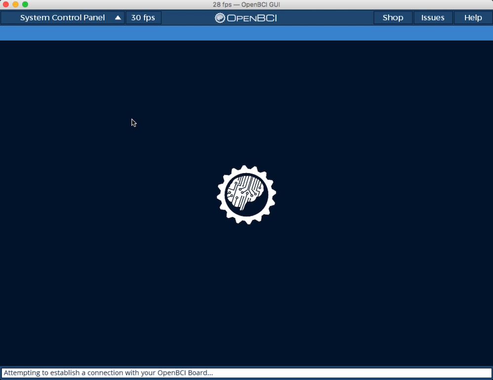
During this time, the help line at the bottom of the OpenBCI GUI should be blinking the words: "Attempting to establish a connection with your OpenBCI Board..."
TROUBLESHOOTING
If the initialization fails, try the following steps in order:
- Making sure you've selected the correct serial/COM port
- Power down your Cyton board and unplug your USB Dongle. Then, plug back in your USB Dongle and power up your Cyton board in that order. Then try restarting the system, but pressing the START SYSTEM button again.
- If this does not work, try relaunching the OpenBCI GUI application and redo step 2 above. Then reconfigure the SYSTEM CONTROL PANEL settings, and retry START SYSTEM.
- Make sure that your batteries are fully charged and then retry the steps above.
- If the channel number is not being displayed, select "AUTOSCAN" from the RADIO CONFIGURATION settings.
- If you are still having troubles connecting to your Cyton board, refer to the Forum for extra troubleshooting advice.
7. Your Cyton is now live!
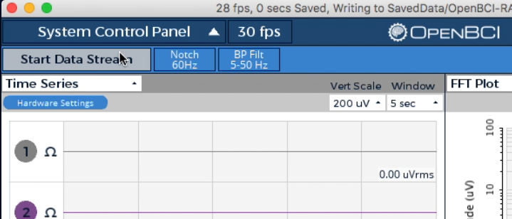
Now that the OpenBCI_GUI is connected to your Cyton you may press Start Data Stream in the upper left hand corner.
You should see data streaming into the GUI. Try running your fingers along the electrode pins at the top of your board.
You should see the 8 (or 16 if you're using a Daisy module) channels on the Time Series widget behave chaotically in response to you touching the pins, and all the traces of the FFT graph on the upper right should instantly shift upwards.
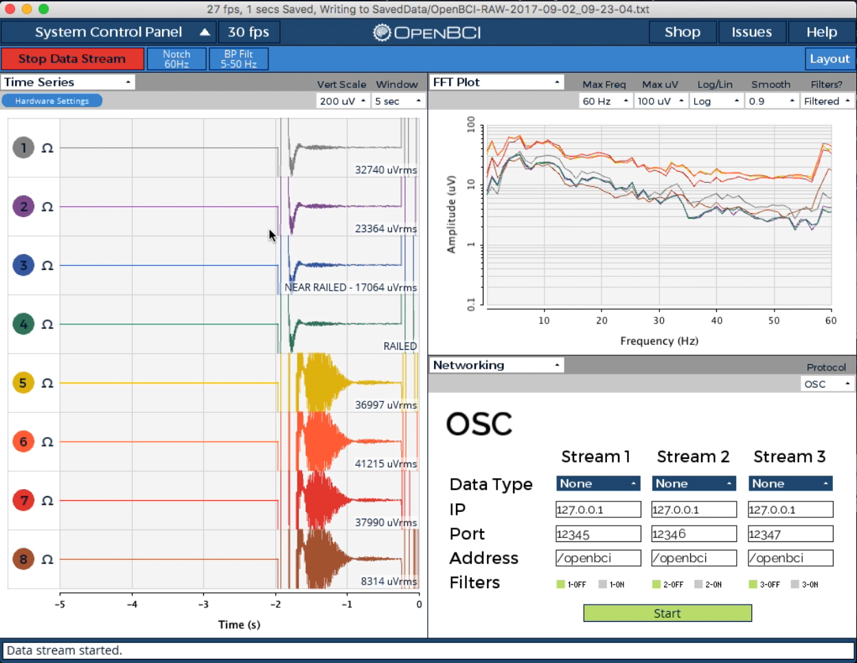
If this is the case, congratulations! You are now connected to your Cyton board. It's time to see some brain waves! Learn about the Time Series and other built-in widgets in the GUI Widget Guide.
By default, the GUI stores all user data and raw EEG recordings in [USER]/Documents/OpenBCI_GUI and names each session with an autogenerated timestamp by default.
Experts and those interested in communicating directly with the board can refer to the Cyton Data Format Guide to learn how to interpret the raw data coming straight from the device. However, this is already handled gracefully by BrainFlow for a number of programming languages and use cases.
V. Connect yourself to OpenBCI
To learn how to connect yourself to OpenBCI using your newly set up board, see the following tutorials:
In the above setups, you may need to adjust the Hardware Settings of the ADS1299 chip, the core piece of technology in the Cyton. Click here for more info on Cyton Hardware Settings UI in the Time Series Widget. If you are an advanced user, you can look at the GUI console log after changing hardware settings and the Cyton SDK Guide to learn how to send custom commands to the Cyton using any BrainFlow binding.
VI. Fixing FTDI Buffering on Mac OS
On some Macs, you may have noticed that the data coming from your Cyton board is very choppy. Newer Macs (mid-2015 and later) may not have this issue and can connect flawlessly to the Cyton using the Dongle sold with each Cyton.
This is a result of the FTDI virtual com port (VCP) driver's default settings for macOS. Head over to the FTDI Driver Fix Guide to see how to adjust the settings.
VII. Fixing FTDI Buffering on Windows
The default FTDI latency is too large for EEG applications, making the incoming signal "choppy" and seem as if it's accumulating packets for about a full second before releasing them all at the same time into the serial stream. Head over to the FTDI Driver Fix Guide for Windows to see how to adjust the settings.