Daisy Getting Started Guide
This guide will walk you through getting 16-channel input on your Cyton+Daisy Module
I. SET UP YOUR CYTON BOARD
Refer to the Cyton Tutorial page: Cyton Getting Started Guide.
Follow the guide through the end of Step V. CONNECT YOURSELF TO OPENBCI
II. WHAT YOU NEED
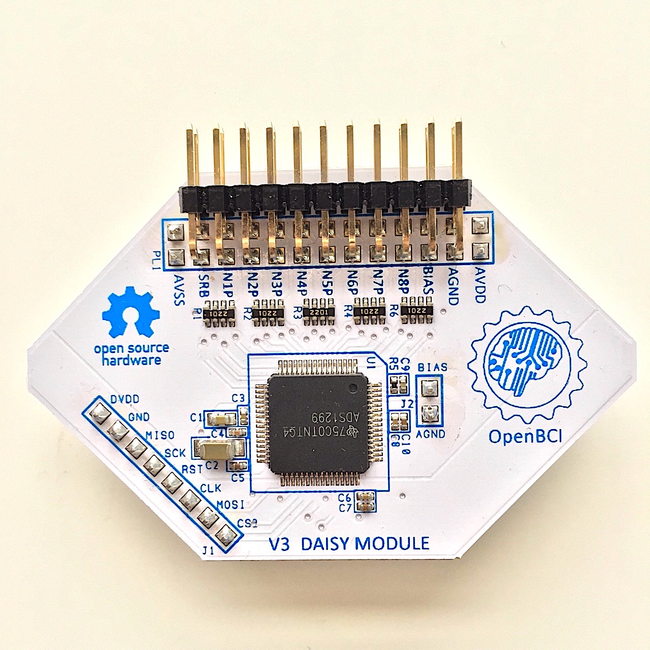
- OpenBCI Daisy Module
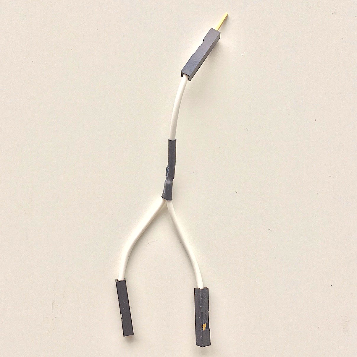
- Y-Splitter Cable
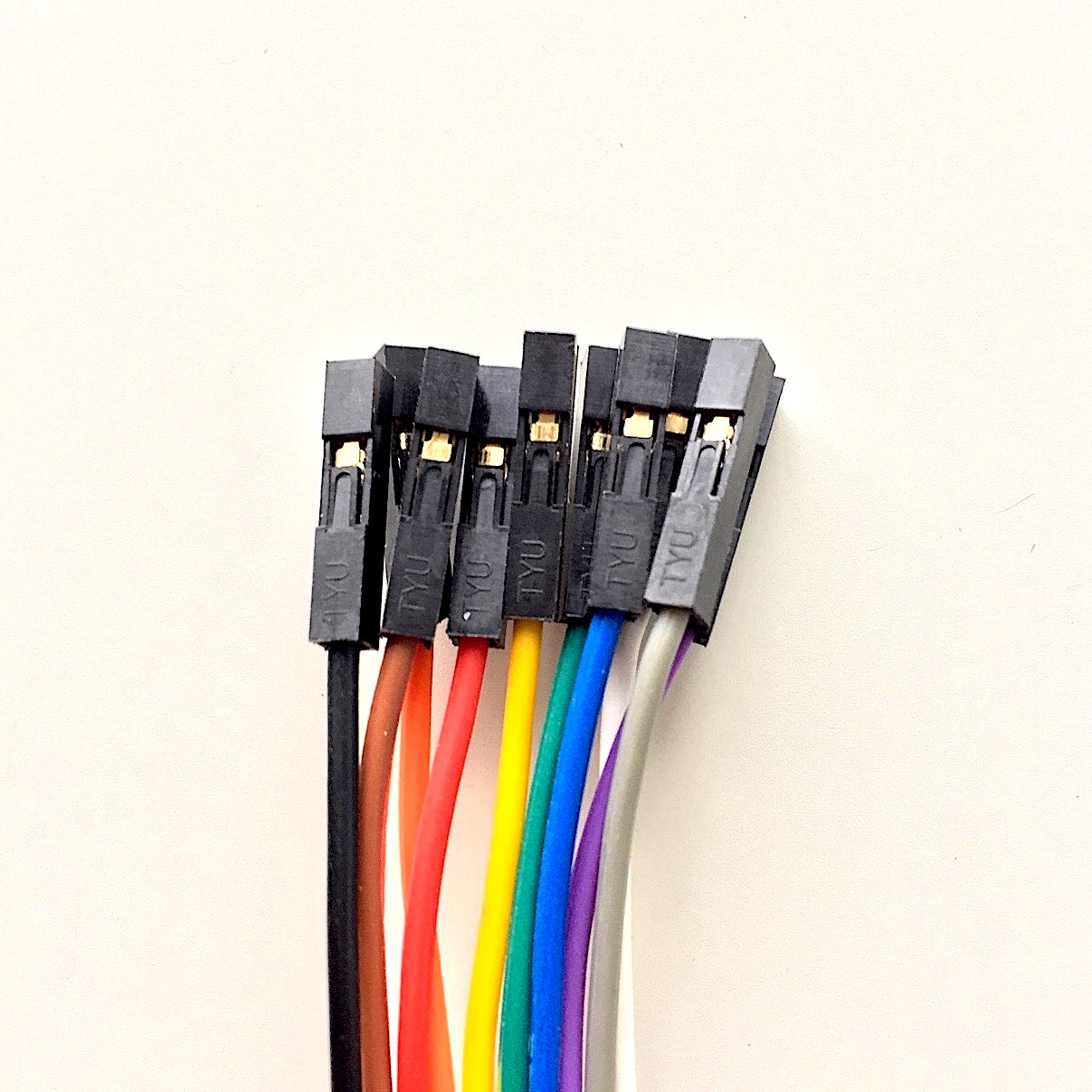
- Electrode cables with female header termination on one end
1. OpenBCI Daisy Module
2. Y-Splitter Cable
3. Electrode Cables with female header termination on one end
III. ASSEMBLY
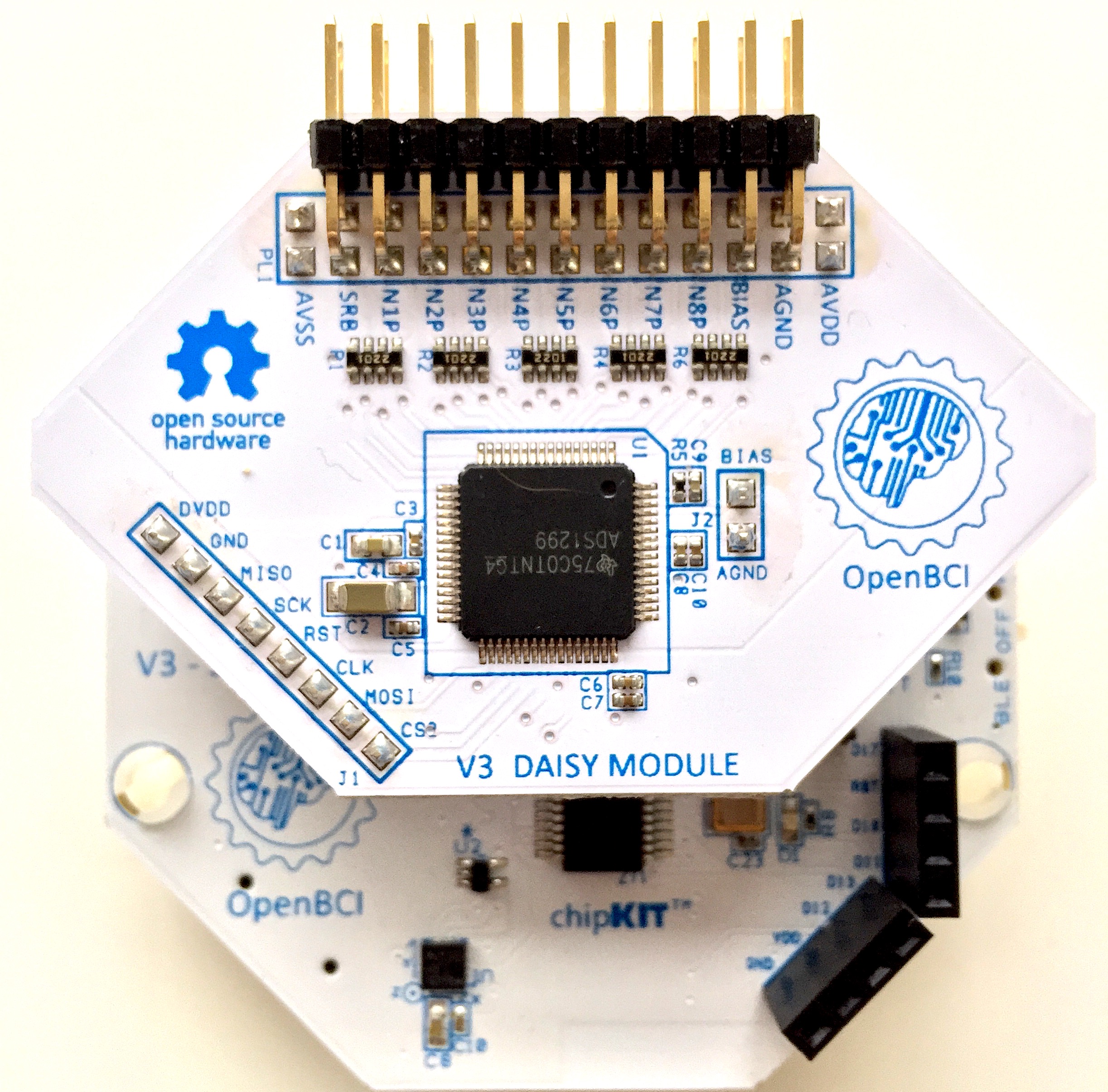
1) Attaching the Daisy
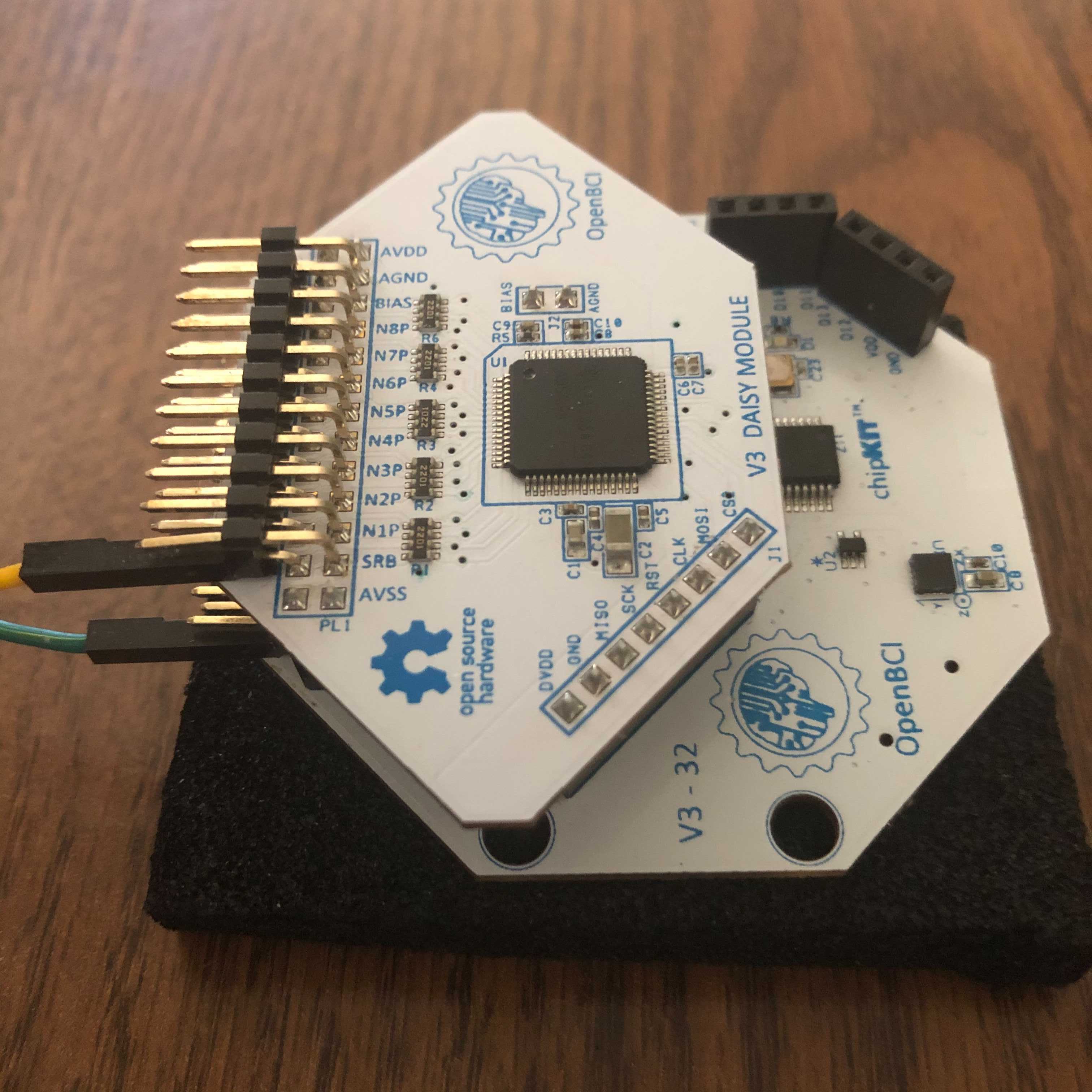
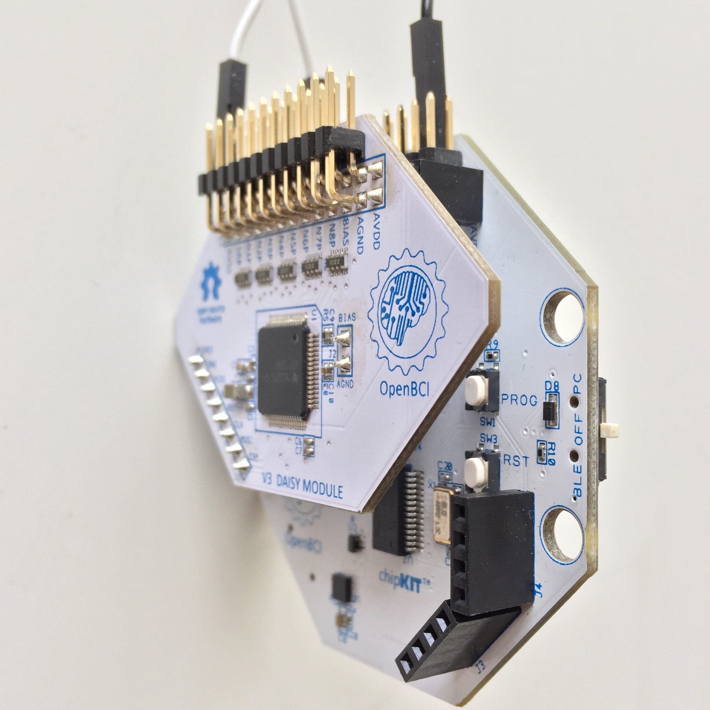
Add the Daisy extension directly onto the Cyton Board
Carefully stack the Daisy module on top of the Cyton Board, as shown below.
2) Connect Y-Splitter Cable
The Y-Splitter connects the bottom SRB pin of the Daisy Board to the bottom SRB pin of the Cyton Board. The single end of the Y-Splitter connects to a reference point i.e. the earlobe or mastoid bone.
3) Connect the bottom BIAS pin of the Cyton to a second reference point
Usually, the earlobe or mastoid is used as the reference point, because it has no muscle or neurons and therefore low electrical signals.
4) Connect Cyton bottom pins N1P-N8P and Daisy bottom pins N1P-N8P to leads
Use the 16 of the color coded cables that came with your Ultracortex MarkIV headset. Alternatively, you can use 16 of our Gold Cup Electrodes, Snap Electrode Cables, or Header Pin to Touch Proof Electrode Adapter.
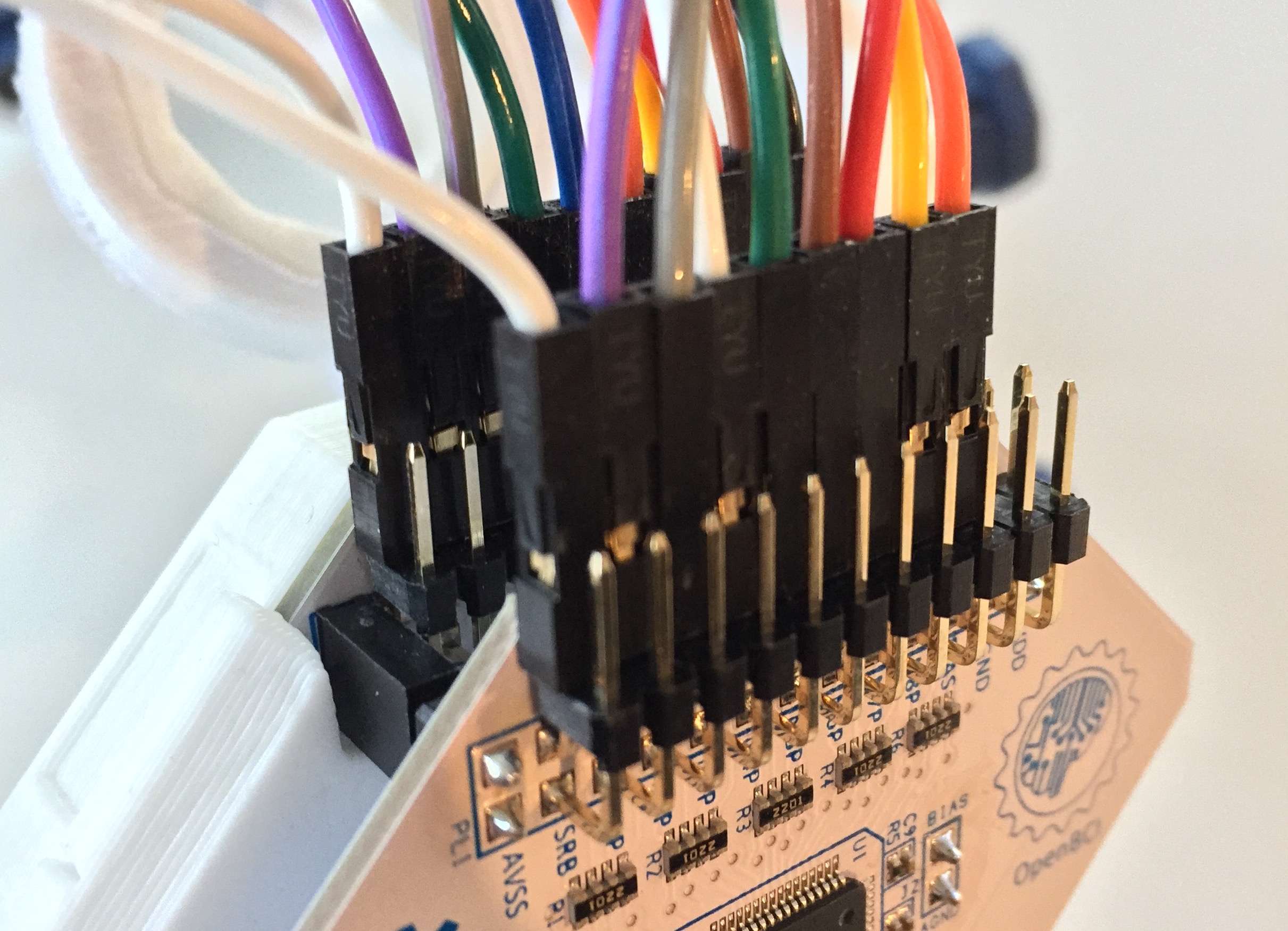
Connect Cyton bottom pins N1P through N8P to the cables, shown above. Then, connect the remaining 8 cables to Daisy bottom pins N1P through N8P. the cable colors should be in this order: gray, purple, blue, green, yellow, orange, red, and brown.
For best results, when plugging female header pins onto the OpenBCI board, orient the sides with the 'silver latch bit' facing toward you since that side is a tiny bit wider than 0.1".
Refer to the Ultracortex Mark IV tutorial to learn how to connect the male terminations of the color coded cables to the electrodes on the headset.