Setting up for EEG, EMG, and ECG at the same time
The OpenBCI Cyton, Cyton+Daisy and Ganglion boards offer a wide range of flexibility to collect ExG signals. ExG is meant to represent any referential or differential biosignal as a single term. This includes EEG, EMG, EOG, ECG etc. This tutorial will show you how to measure EEG, ECG and EMG at the same time using the Cyton, Cyton+Daisy and Ganglion boards.
After going through this tutorial, you will learn how to configure the OpenBCI boards to measure multiple ExG recordings at the same time. You could apply the same principle to build channel layouts to fit your application (i.e., 3-lead ECG vs. 5-lead ECG; eight or more EEG channels etc).
Background Information
Before starting this tutorial, we recommend you go through at least one of the following guides to familiarize yourself with the OpenBCI system before starting this tutorial:
- EEG: scalp surface recording brain activity. Learn more
- EMG: forearm measurement of muscle nerve signals Learn more
- ECG: measure heart rhythm on the chest Learn more
ECG and EKG are used interchangeably and mean the same thing. Both terms measure the electrical activity of the heart muscles.
Referential and Differential Signals with the ADS1299
EEG, EMG, and ECG have different input requirements. This is because EEG is referential and EMG and ECG are differential. Referential biosignals are those that measure signals from an electrode location with a common reference point (like the earlobe). Differential biosignals are those that are localized to a certain area and the measured signal is the difference in voltage generated at that area. EEG is a referential signal because the signal is measured between an electrode location on the scalp and an electrically inert part of the head like earlobes, bridge of the nose etc. EMG and ECG are differential signals because two electrodes are used to measure the signal of a particular muscle on the body or heart.
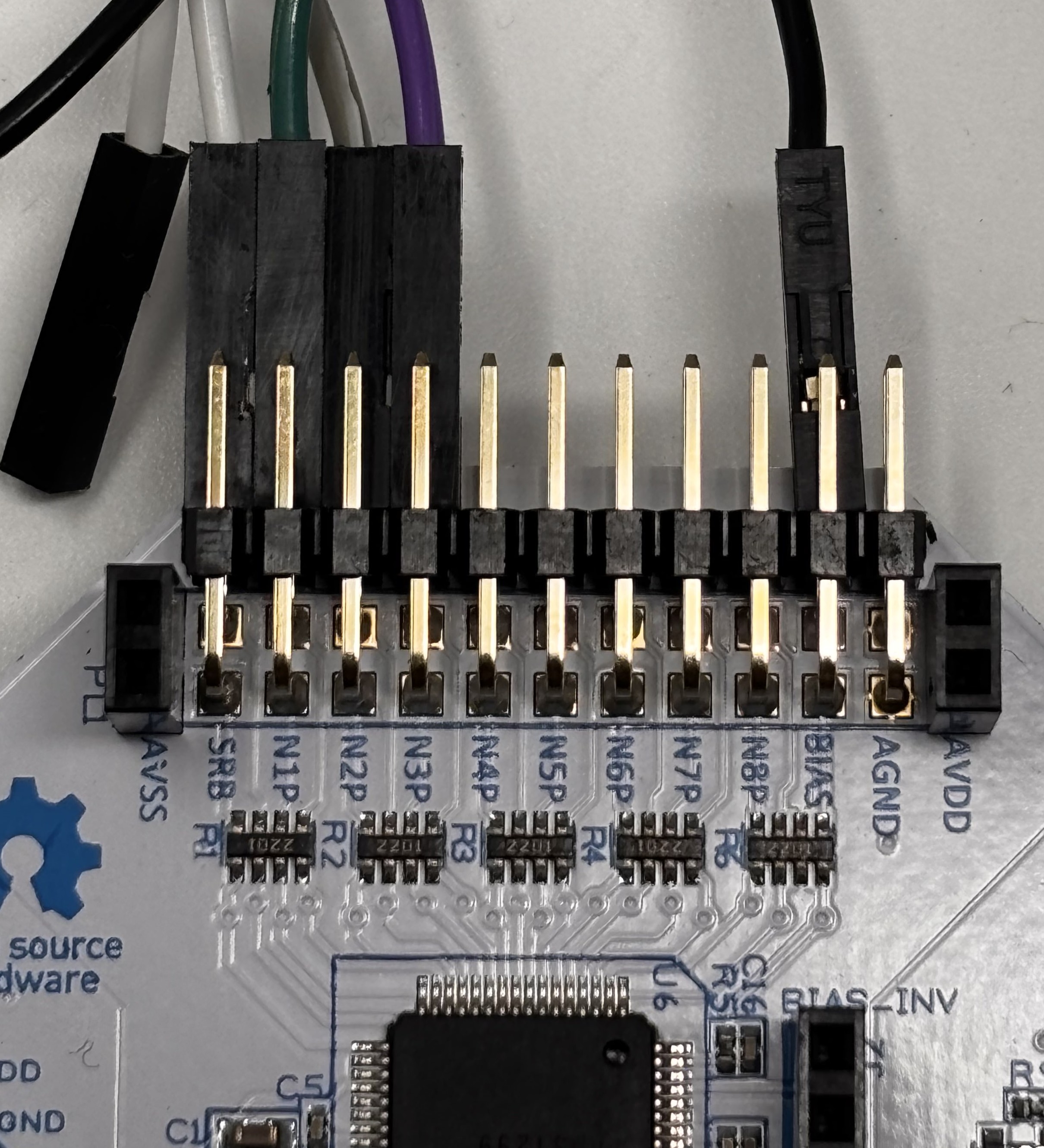
The labels for the channels can be found below the pin on the boards. Here we call BIAS and SRB the reference channels as they provide reference to the data channels. The data channels are N1P-N8P. The data streams come from the data channels. Each channel come with a top and bottom pin 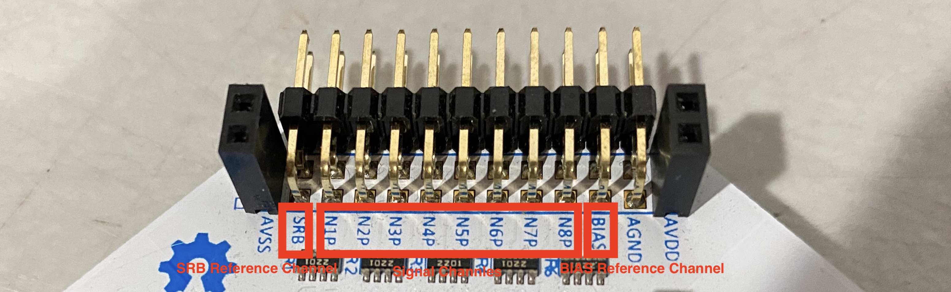
Here are the reference channels needed for EEG, EMG, and ECG, respectively.
- EEG: two reference channels - one SRB, and one BIAS
- ECG and EMG: one reference channel - BIAS
The BIAS and SRB are functions of the ADS1299 and this functionality provides the flexibility to measure differential and referential signals at the same time. SRB stands for Stimulus, Reference and Bias and acts as a common point for referential signals like EEG to compare against. SRB has two different pins on the ADS1299 - SRB1 and SRB2.
SRB1 acts as a common reference for all the Positive inputs (meaning that it connects all the Negative inputs internally to the SRB1 pin) and SRB2 acts as a common reference for all Negative inputs (meaning that it connects all the Positive inputs internally to the SRB2 pin). To measure EEG with the Cyton and Cyton+Daisy, we use SRB2 as the common reference because it has the flexibility to be used individually for each channel instead of SRB1 which does not provide individual control. Therefore, the EEG measurements will look like (SRB2 - Negative Input) which is why the EEG signals might look inverted.
BIAS on the other hand is used for noise-canceling due to connecting all Positive inputs to a common reference point. When doing this, a phenomenon called "Common Mode Noise" leaks into the board because multiple inputs are connected to the same point. Therefore, a BIAS connection to the body helps the ADS1299 account for this and a common mode voltage is subtracted from all measurements. It also helps in filtering out 50/60 Hz mains noise which is why we use it in all our referential and differential biosensing setups.
For more information on SRB2, refer to Section 9.3.1.1 - Input Multiplexer and for more information on BIAS, refer to Section 9.3.2.4.5 - BIAS Drive of the ADS1299 Datasheet
ExG Measurement with Cyton+Daisy boards
The Cyton and the Daisy boards both use the ADS1299 which makes this setup very simple and flexible. You just need to make sure that the settings in the OpenBCI GUI are correct so that the appropriate channels are configured properly. You can also setup just the Cyton to measure EEG, EMG and ECG. For simplicity, this section will use both the Cyton and the Daisy boards.
Here's a list of material you will need for this tutorial:
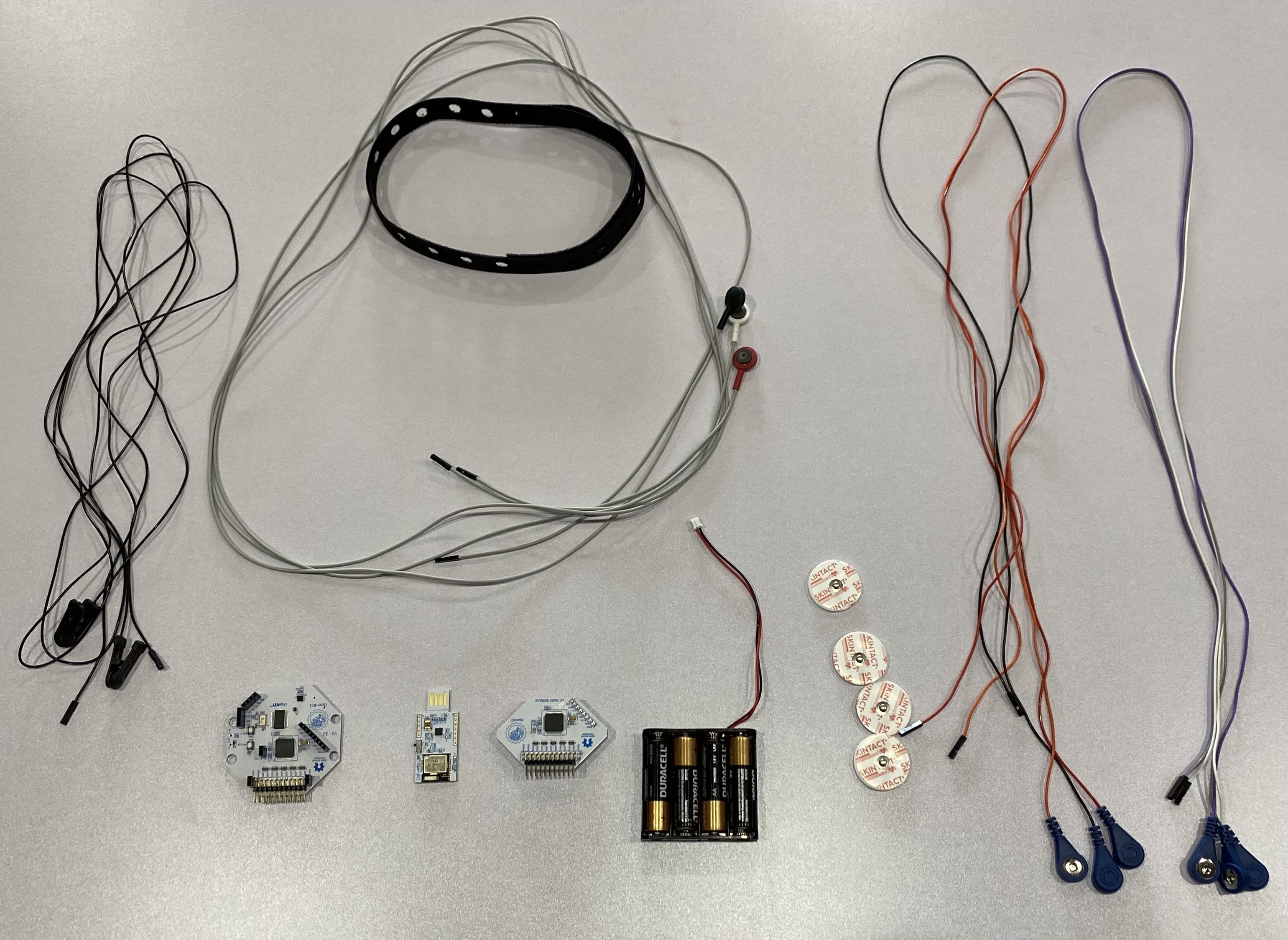
- EEG hardware, can be one of the following Ultracortex Headband kit , Ultracortex Mark IV , Ultracortex Mark III , Electrode Cap; we will be using the Headband kit in this tutorial.
- EMG/ECG hardware including Solid Gel Electrodes or IDUN Dryode and Snap Electrode Cables (EMG/ECG/EEG)
- OpenBCI Cyton, Cyton + Daisy
- Y-Jumper Cable. This is required only when using a Daisy board with the Cyton and is usually included when you buy a Cyton+Daisy Kit.
- Cyton Bluetooth Dongle
- Computer with OpenBCI GUI
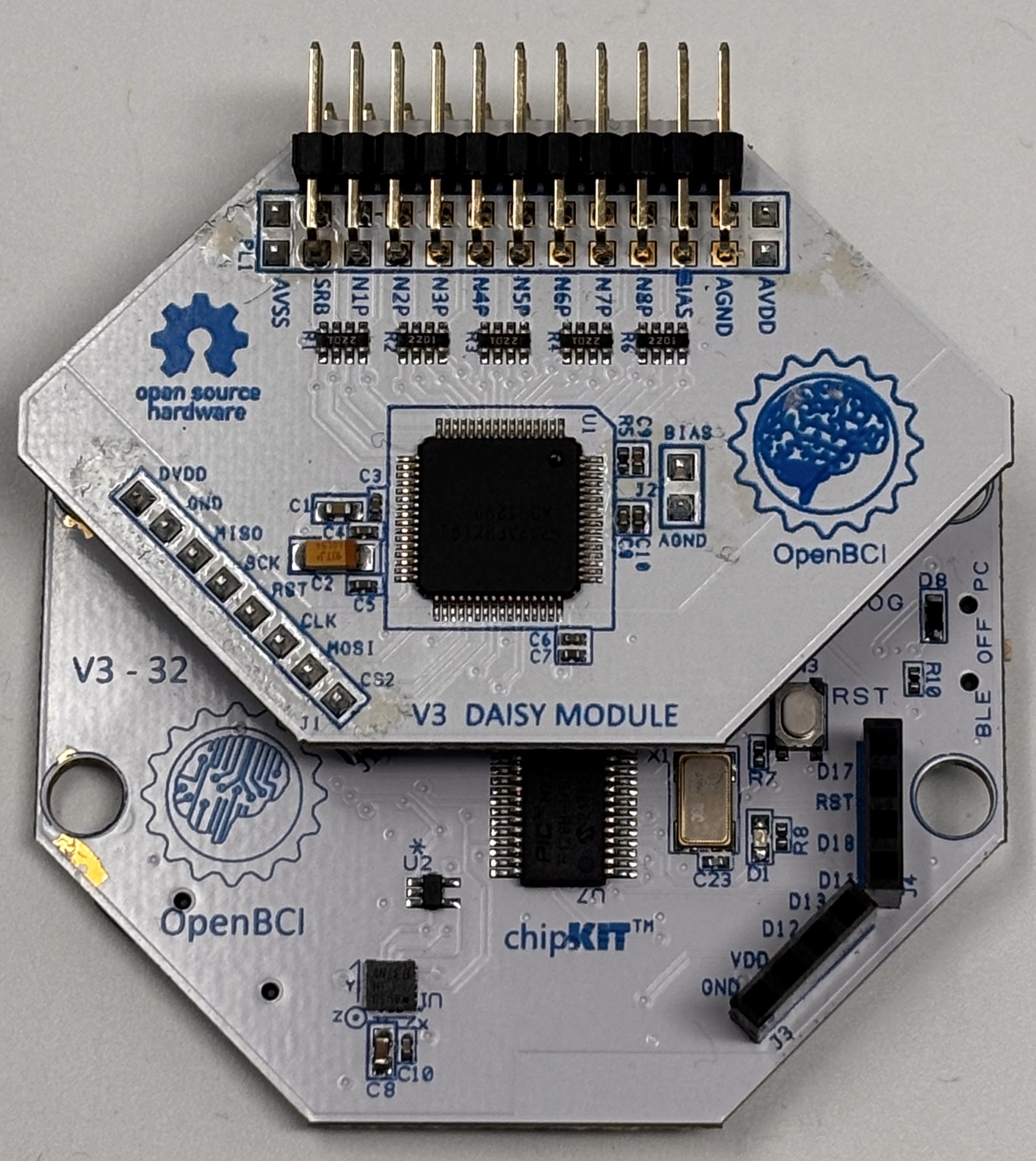
In this tutorial, we will use the Cyton to measure EEG, and the Daisy to measure EMG and ECG. First, attach the Daisy to the Cyton board if they are not already attached. Be sure to attach them correctly as shown below
Setting up 3-channel EEG
In this section, we will show you how to connect the EEG electrodes to the Cyton to measure EEG. You can later increase the number of EEG channels based on your needs as long as there are enough input headers (N1P-N8P) on the board.
As shown in the below image, connect the EEG electrodes to Channels 1, 2 and 3 of the Cyton by connecting them to the bottom row of the N1P, N2P and N3P pins. Then, connect an earclip electrode to the bottom BIAS pin and a Y-jumper to the bottom SRB pin.
Setting up EMG and ECG
For EMG and ECG, we set this up on the Daisy board. Since EMG and ECG are differential signals, both the top and bottom input header pins are required. For this tutorial, we will use 1 channel for EMG and another one for ECG.
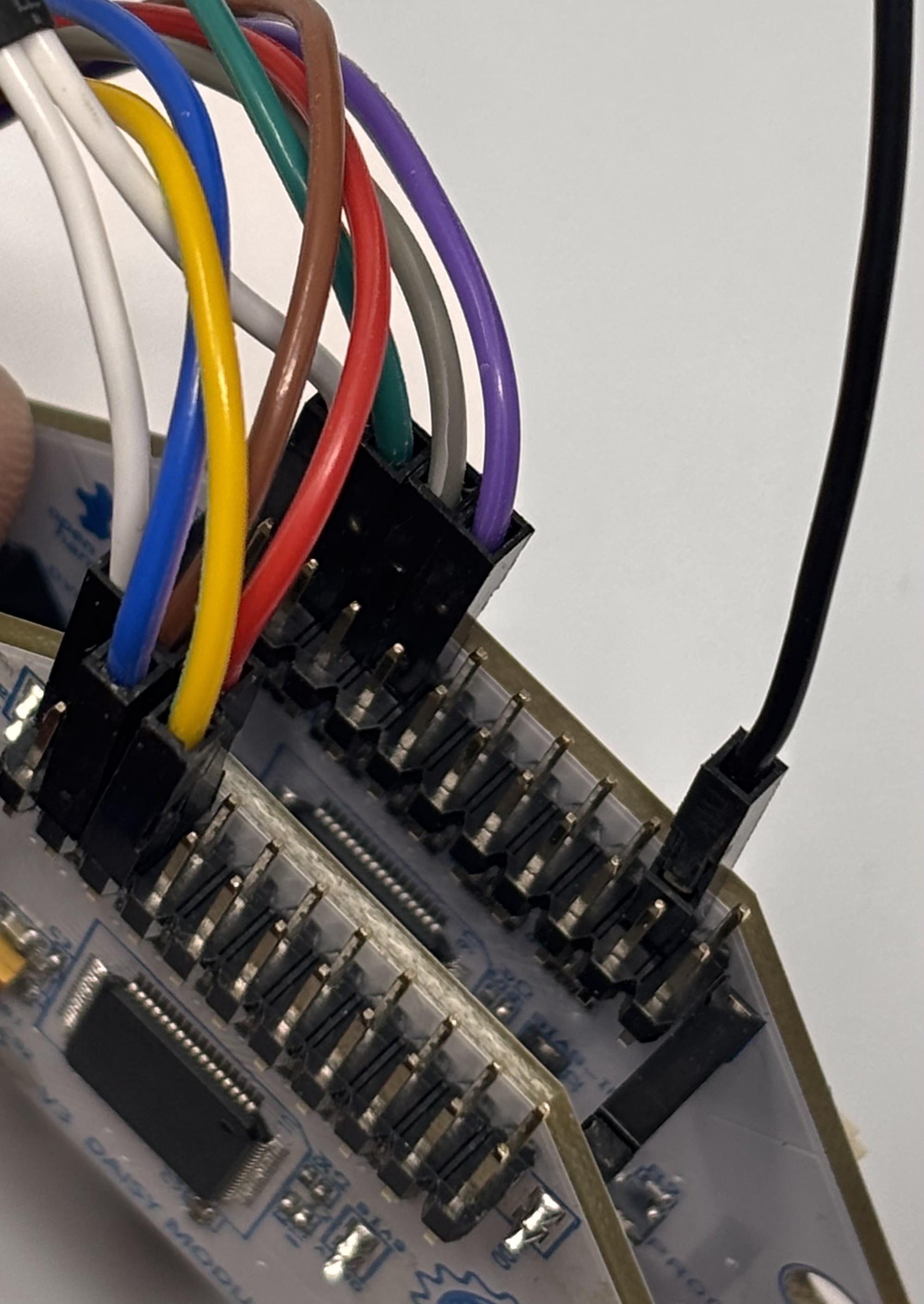
For ECG, connect two cables to N1P top and bottom pin and connect the other end of the Y-Jumper cable to bottom pin of SRB. Attach the electrodes to your chest, the recommended layout is described in the ECG tutorial. For note on ECG signal quality, you can refer to the section Improving Signal Quality in the ECG tutorial.
For EMG, connect two cables to N2P top and bottom pin. Attach the electrodes to your arm, the recommended layout is described in the EMG tutorial.
Please refer to the ECG tutorial for alternative 5-lead ECG setup.
The complete setup should look like this
Visualize the data in OpenBCI GUI
If you don't have the GUI installed, please refer to this guide to learn about how to set up the OpenBCI GUI for your operating system. Connect the battery to the Cyton or Cyton+Daisy and power on the board and connect the USB dongle to your computer (make sure the dongle switch is set to GPIO_6).
Next, open the OpenBCI GUI and click the following:
- Select CYTON (live)
- Serial (from Dongle)
- 16 CHANNELS
- Click AUTO-CONNECT and the board should be connected to the GUI.
If you are using just the Cyton, select the 8 Channel option. Since we are using both the Cyton and the Daisy for this tutorial, we select 16 Channel Mode. We also do not need all 16 Channels. Therefore, before starting a data stream, turn off the channels that are not being used by clicking on the Channel number and hide them from the Time Series Widget as shown below.
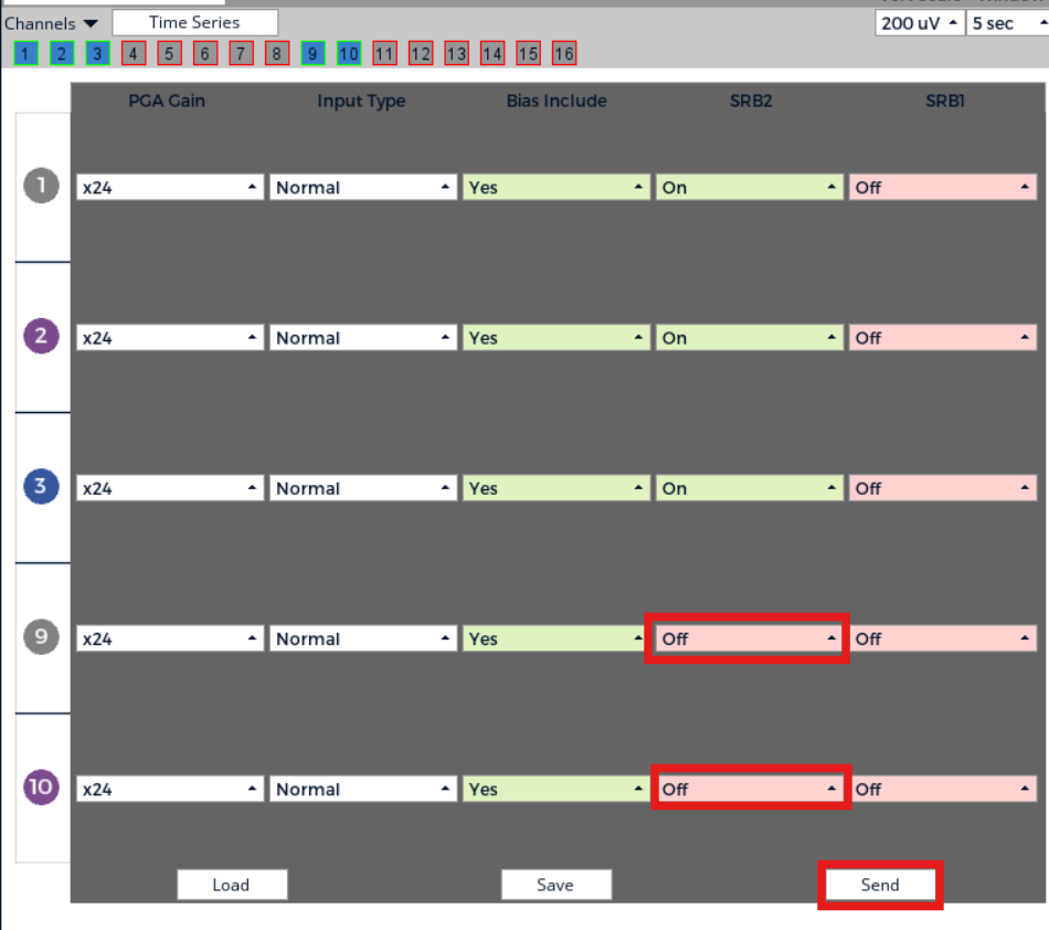
Also, before starting a data stream, remember that you need to select SRB2 for those channels that are EEG and deselect SRB2 for those channels that are EMG or ECG as shown below. For channels that are turned off, this does not matter as they will not be collecting data. But, if you change the channel configurations you must also select and deselect SRB2 accordingly. If you do not, then the data will not look right because the reference is wrong. After you are done changing the HW Settings, send these settings to the board by pressing "Send".
Now click "Start Stream" and you should see EEG, EMG and ECG signals on the channels that have been configured so as shown below. In the example, you will first see an EMG activation then followed by Alpha waves in EEG channels. The ECG is present in Channel 9.
ExG Measurement with Ganglion boards
The Ganglion board uses the MCP3912 ADC chip and does not have the flexibility that the ADS1299 chip has to change configurations through software. But, you can still change the Ganglion board input pins to act as referential or differential inputs based on hardware select switches present on the board. For more information on how to use the select switches, refer to this guide.
The Ganglion board is a 4 channel board and so, for this tutorial, we will measure 2 channels of EEG, 1 channel of ECG and 1 channel of EMG at the same time. For this tutorial, you will need the following materials.
- EEG hardware, can be one of the following Ultracortex Headband kit , Ultracortex Mark IV , Ultracortex Mark III , Electrode Cap; we will be using the Headband kit in this tutorial.
- EMG/ECG hardware including Solid Gel Electrodes or IDUN Dryode and Snap Electrode Cables (EMG/ECG/EEG)
- OpenBCI Ganglion board.
- Ganglion Bluetooth Dongle (if using an older version of MacOS).
- Computer with OpenBCI GUI
Setting up EEG, ECG and EMG
For this tutorial, we will use Channels 1 and 2 as EEG, Channel 3 as ECG and Channel 4 as EMG. So, push the input select switches for Channels 1 and 2 to the DOWN position and push the input select switches for Channels 3 and 4 to the UP position. If you are having trouble pushing the switches, use a pair of tweezers to help you. After configuring the channels, the switches should be in the positions as shown below.
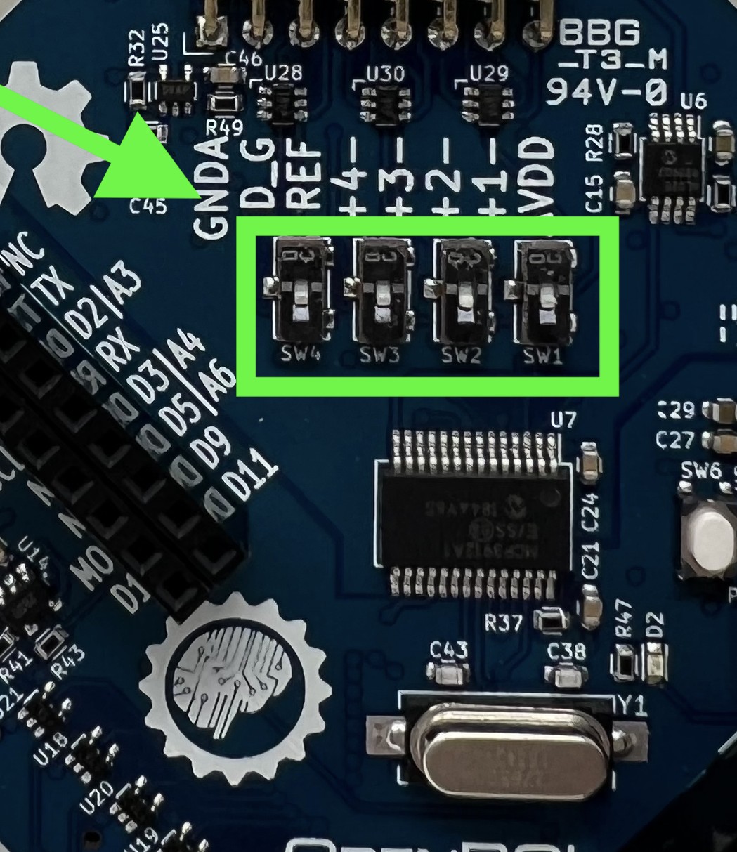
The Ganglion board also has a REF and D_G pin which act exactly as the SRB2 and BIAS pins in the Cyton and Cyton+Daisy. The REF pin acts as a common reference when measuring EEG and the D_G pin acts as the BIAS pin for cancelling common-mode noise and 50/60 Hz noise. Although there is a top and bottom pin for REF and D_G, these are the same pins are can be used for any setup. For ease of use, we will use the top pins of REF and D_G.
For EEG, connect the top pins of +1- and +2- headers to the EEG electrodes and the top pins of the REF and D_G pins to the earclips. For ECG and EMG, connect the top and bottom pins of the +3- and +4- headers to the Snap electrode cables and connect them to ECG electrode locations and EMG electrode locations. The final pin connections should be as shown below.
| Front View | Top View |
|---|---|
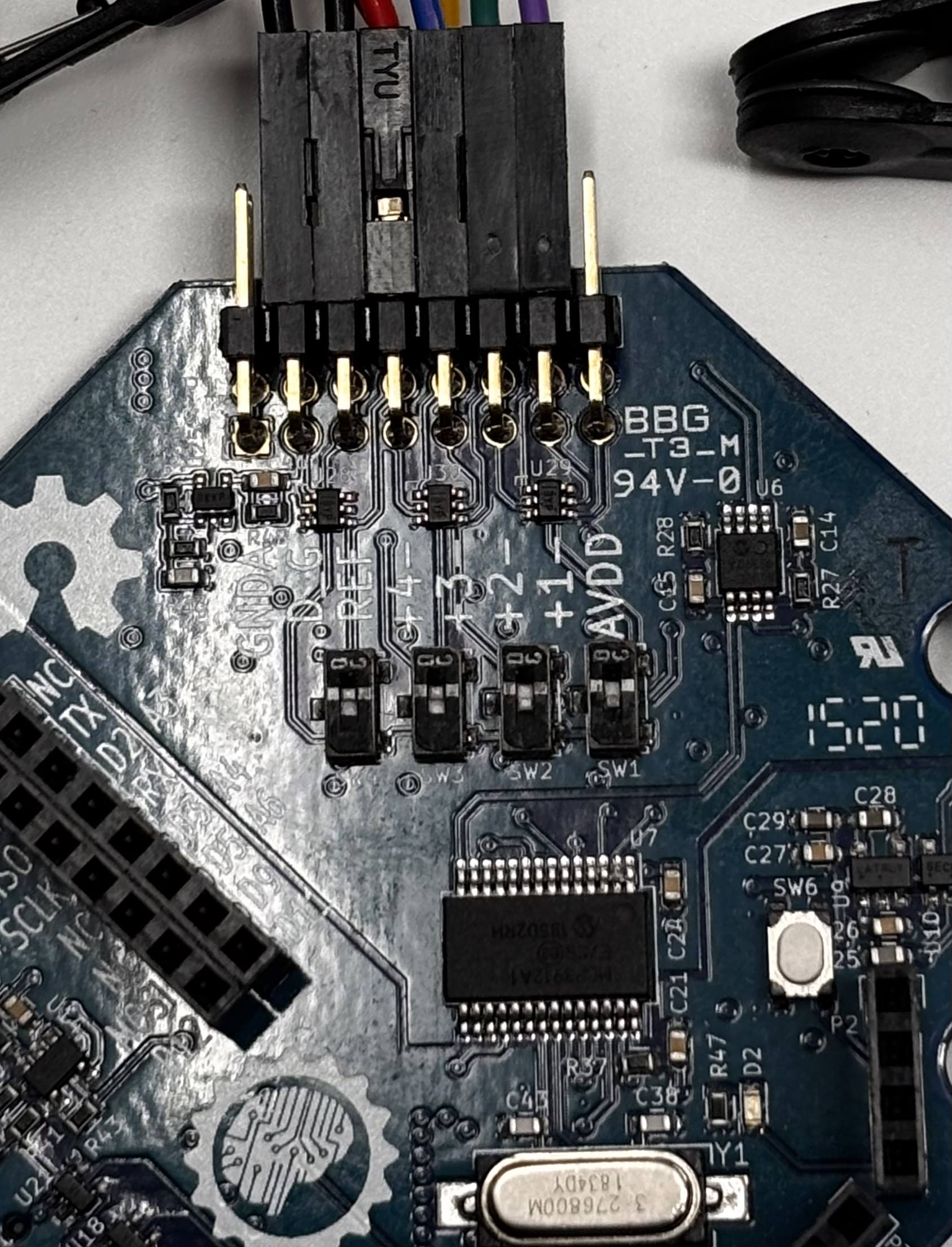 | 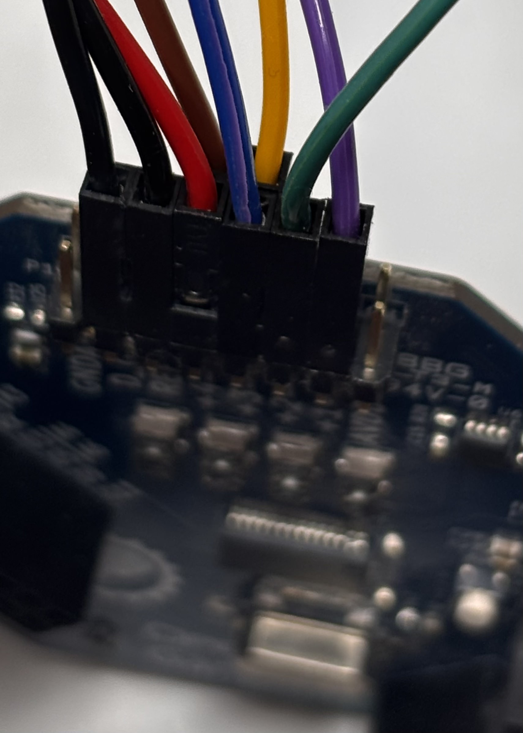 |
When using EEG with another differential signal, the earlobe location can be used as a BIAS for a differential signal. But, if you are facing signal quality issues with the differential signal, you can connect a sticky electrode at a bony part near the differential signal to the other D_G pin.
Visualize the data in the OpenBCI GUI
If you don't have the GUI installed, please refer to this guide to learn about how to set up the OpenBCI GUI for your operating system. Connect the battery to the Ganglion board, power on the board and connect the Ganglion USB dongle to your computer.
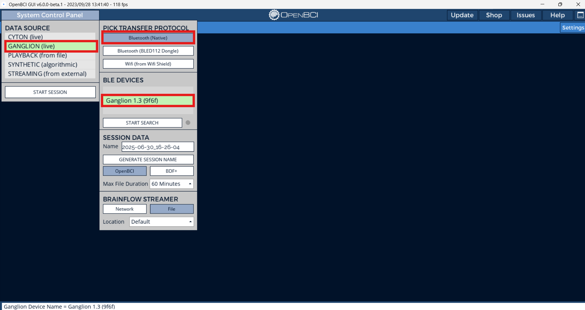
Next, open the OpenBCI GUI and click the following:
- Select Ganglion (live)
- Bluetooth (Native)
- Select your Ganglion from the BLE Devices list
- Click START SESSION and the board should be connected to the GUI
You do not need to change any hardware settings through software for the Ganglion and you are using all 4 channels which means you do not need to turn off or hide any channel. Make sure that the input select switches are in the right position because an incorrect position will cause data issues and you will not see biopotential measurements in the GUI. Also, for some older versions of Mac, you will need to use the Ganglion Dongle to connect to the Ganglion Board. If you require the dongle, just use the BLED112 Dongle option instead.
Now click Start Session, and then Start Data Stream. You should see EEG, EMG and ECG signals on the channels that have been configured so as shown below. You can see the ECG signal in Channel 3, the EMG activations in Channel 4 and Alpha waves in Channel 1 and 2.