Ultracortex Mark III
Development Period: June 2016
Complete Ultracortex Mark 3 kits are not longer available for sale in the OpenBCI Online Store. We have phased out production. You can find the latest headset here.
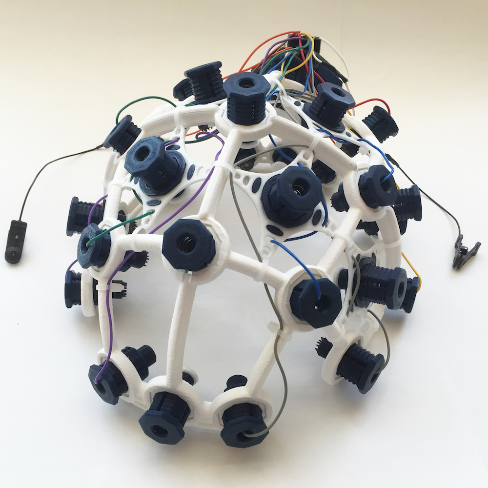
The Ultracortex is an open-source, 3D-printable headset intended to work with the OpenBCI system. It is capable of recording research-grade brain activity (EEG), muscle activity (EMG), and heart activity (ECG). The Ultracortex is under constant iteration. If you print/assemble your own Ultracortex, we would love to hear your feedback. Send us an email at contact@openbci.com or Tweet at us (@Ultracortex & @OpenBCI)!
Designers & Engineers:
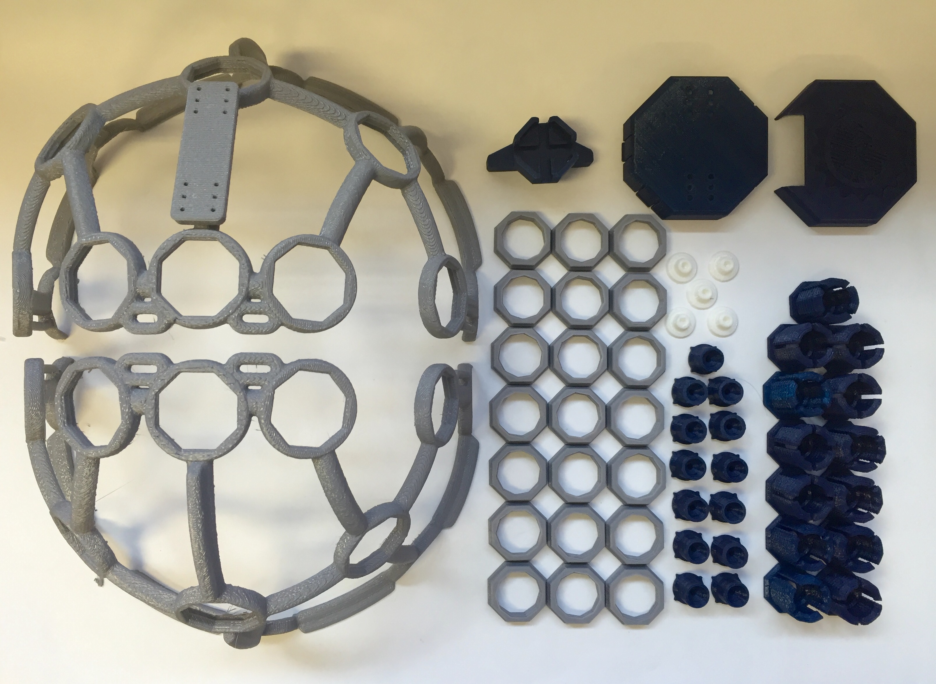
THE COMPLETE ULTRACORTEX
Note: the part quantities listed below assume you are making an electrode holder for all 21 nodes of the Ultracortex Mark 3. In reality, you will likely have only 8 or 16 electrodes, depending on whether you are working with the OpenBCI Cyton Board (8 channels) or the OpenBCI CytonDaisy Board (16 channels). You may only want to create as many electrode units as you have channels, and then add more as necessary. In general, more electrodes will distribute the downward scalp pressure, increasing comfort.
3D-printed Parts:
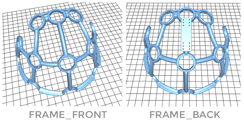
- FRAME (head circumference: small = 50-55cm, medium = 55-60cm, large = 60-65cm)
- MECH_PARTS
- OCTANUT (x21) — .STLs (tight / normal / loose) (Choose normal first / if it is too tight for the OCTABOLT, choose loose / if it is too loose for the OCTABOLT, choose tight)
- OCTABOLT (x21) — .STL download link
- OCTARING (x21) — .STL download link
- ELECTRODE_HOLDER (x21) — .STL download link
- QUADSTAR (x21) — .STL download link
- Comfy Insert (x21) — .STL download link
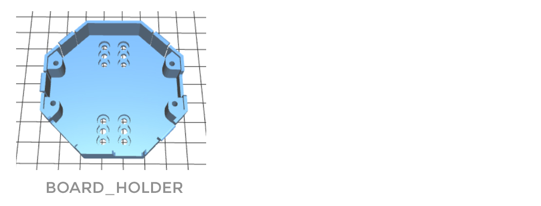
- BOARD_HOLDER (x1) — .STL download link
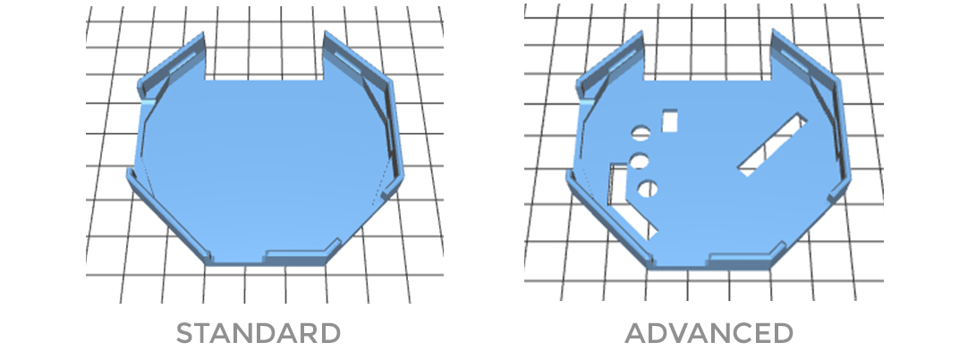
- BOARD_COVER (x1) — choose STANDARD or ADVANCED
- STANDARD — .STL download link
- ADVANCED (for extra hardware accessibility / if you've soldered on your header rows) — .STL download link
- OCTATOOL (x1) — .STL download link
Non-printed Parts:
- Additional Hardware:
- Suggested Spring 1 listed below (x21)
- Suggested Spring 2 listed below (x5)
- Suggested Nuts listed below (x42)
- Suggested Bolts listed below (x21)
- 1/4" #4 Drive Screw listed below (x8) for mounting the BOARD_HOLDER and OpenBCI Board
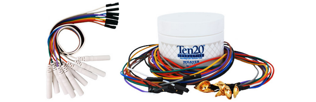
- Wiring (x21)
- We strip apart the Gold Cup Electrodes or the Touch-Proof Adapter Cables..
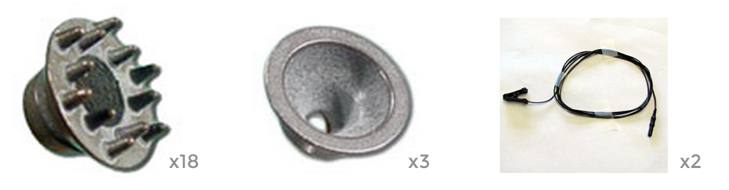
- Three types of dry electrodes needed
- (18x) Dry (spikey) electrodes to be installed in Ultracortex nodes with hair: 5 mm Ag/AgCl Comb Electrodes
- (3x) Dry (non-spikey) electrodes to be installed in Ultracortex nodes without hair (forehead, for instance): Disposable / Reusable Cup Wet/Dry EEG Electrode ($10.00 for 15)
- (2x) Ear Clip electrode (for reference): TDI-430 Silver-Silver Chloride Ear Clip Electrode ($19.95 each)
- (1x) An OpenBCI Cyton Board (8-channel) or an OpenBCI CytonDaisy Board (16-channel)
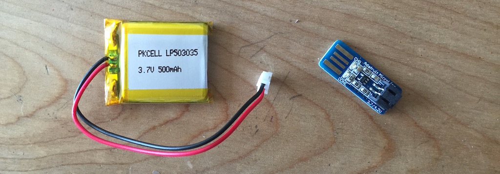
- (1x) Lithium Ion Rechargeable Battery Pack (~500mAh) — Sparkfun or Adafruit
- (1x) A charger for your battery pack
- (~10x) Zip tie
THE COMPLETE ULTRACORTEX (w/ PICTURES)
3D-printed Parts:
(1x) FRAME
- FRAME (head circumference: small = 50-55cm, medium = 55-60cm, large = 60-65cm)
(21x) MECH_PARTS
- MECH_PARTS
- OCTANUT (x21) — .STLs (tight / normal / loose) (Choose normal first / if it is too tight for the OCTABOLT, choose loose / if it is too loose for the OCTABOLT, choose tight)
- OCTABOLT (x21) — .STL download link
- OCTARING (x21) — .STL download link
- ELECTRODE_HOLDER (x21) — .STL download link
- QUADSTAR (x21) — .STL download link
- Comfy Insert (x21) — .STL download link
(1x) BOARD_HOLDER
(1x) BOARD_COVER
- BOARD_COVER (x1) — choose STANDARD or ADVANCED
- STANDARD — .STL download link
- ADVANCED (for extra hardware accessibility / if you've soldered on your header rows) — .STL download link
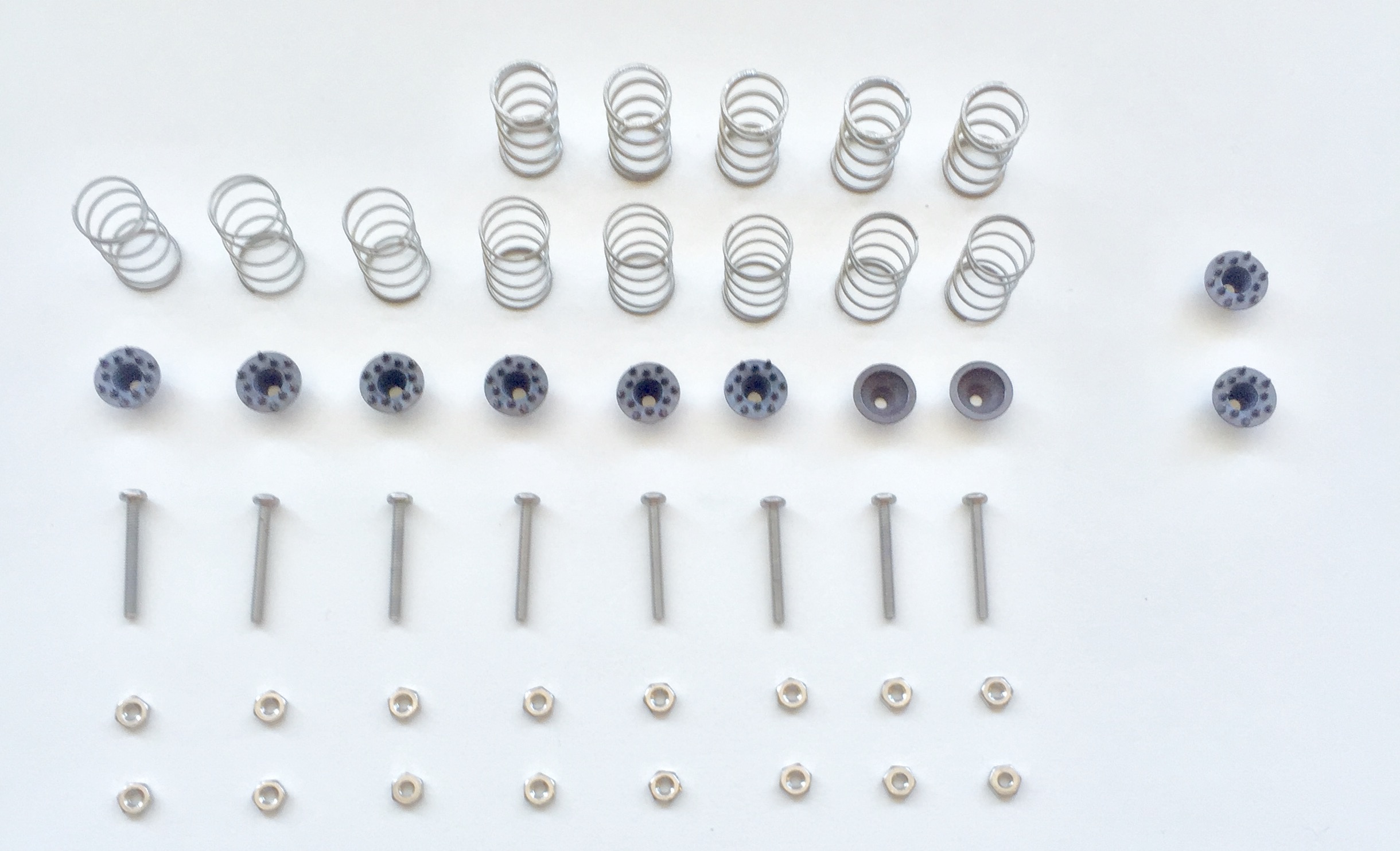
Non-printed Parts:
Suggested Springs:
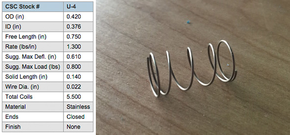
- Suggested Spring 1 (x21) — aka "Weak Spring" — Century Spring Corp. Stock #: U-4. This spring is not as strong as Spring 2. We use it to mount the electrodes. The low "Rate" (1.3 lbs/in) makes it more forgiving and comfortable when holding the spikey electrode against your head. This process is described in more detail below (in the "Assembly Instructions" section).
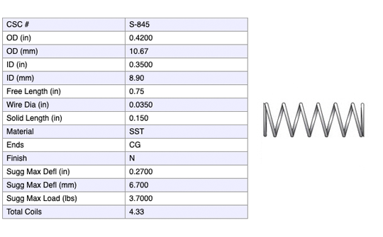
- Suggested Spring 2 (x5) — aka "Strong Spring" — Century Spring Corp. Stock #: S-845. This spring has a much stronger "Rate" (14 lb/in). This makes it ideal to act as a standoff at locations where you do not have a spikey electrode. This process is described in more detail below (in the "Assembly Instructions" section).
Suggested nuts/bolts:
We use small stainless steel screws and hex nuts to fasten the FRI electrodes (listed above) to the 3D-printed electrode mount components and wiring that connects the electrodes back to the OpenBCI board. We used stripped Gold Cup Electrodes as the cabling, by removing the gold cup with a wire cutter and looping the exposed wire around the screw between the two tightened hex nuts (as seen in the picture below).
- (21x) Stainless Steel Pan Head Phillips Machine Screw, 2-56 Thread, 3/4" Length ($5.70 per pack of 50)
- (42x) Stainless Steel Hex Nut, 2-56 Thread Size, 3/16" Wide, 1/16" High

Suggested screws for fastening BOARD_MOUNT & OpenBCI Board
- (8x) #4 Drive Screw

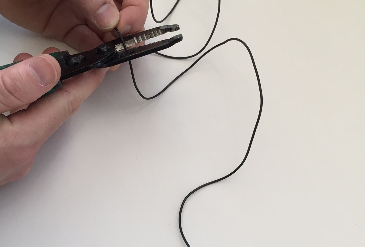
Wiring
- (21x) We strip apart the Gold Cup Electrodes or the Touch-Proof Adapter Cable.
Dry electrodes by Florida Research Instruments
- (18x) Dry (spikey) electrodes to be installed in Ultracortex nodes with hair: Dry 5 mm Comb Electrodes
- (3x) Dry (non-spikey) electrodes to be installed in Ultracortex nodes without hair (forehead, for instance): Disposable / Reusable Cup Wet/Dry EEG Electrode ($10.00 for 15)
- (2x) Ear Clip electrode (for reference): TDI-430 Silver-Silver Chloride Ear Clip Electrode ($19.95 each)
(1x) An OpenBCI Cyton Board (8 electrode channels) or an OpenBCI CytonDaisy Board (16 electrode channels)
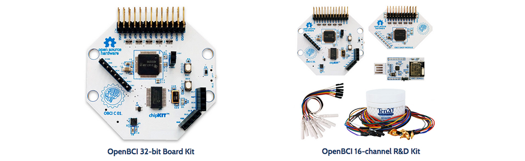
(1x) ~500mAh lithium ion rechargeable battery pack (Sparkfun or Adafruit) & (1x) A charger for your battery pack
(~10x) Zip tie
SUGGESTED PRINT SETTINGS
- FRAME_FRONT & FRAME_BACK
- Material: PLA
- Supports: YES
- Raft: hopefully NO (but if supports aren't sticking, try the raft)
- Infill: 20%
- Layer Height: 0.2mm
- Number of Shells: 3
- Speed while extruding: 50-70% (slow it down if possible; these parts are detailed)
- MECH_PARTS (OCTANUT / BOLT / SPRING_CASING / ELECTRODE_HOLDER)
- Material: PLA
- Supports: NO
- Raft: NO
- Infill: 20%
- Layer Height: 0.2mm
- Number of Shells: 3
- Speed while extruding: 50-70% (slow it down if possible; these parts are detailed)
- BOARD_MOUNT, BOARD_COVER_STANDARD, & BOARD_COVER_ADVANCED
- Material: PLA
- Supports: NO
- Raft: NO
- Infill: 20%
- Layer Height: 0.2mm
- Number of Shells: 3
- Speed while extruding: 50-70% (slow it down if possible; these parts are detailed)
- QUAD_STAR
- Material: NinjaFlex or SemiFlex
- Supports: NO
- Raft: NO
- Infill: 10%
- Layer Height: 0.27mm (or 0.3mm)
- Number of Shells: 2
- Speed while extruding: 30-50% (slow it down if possible; these parts are detailed)
- Print Temperature: 230-250C (we get more consistant prints when printing at higher temperatures, but it gets stringy)
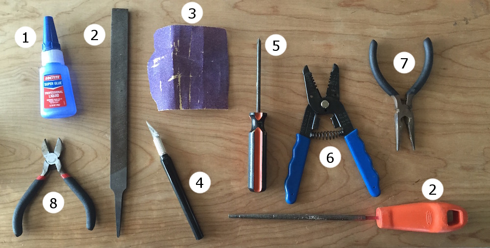
RECOMMENDED ASSEMBLY TOOLS
- Loctite Super Glue w/ Cyanoacrylate
- coarse flat & circular files (for removing support artifacts)
- medium sand paper
- exacto blade
- philips head screw driver
- wire cutters
- needle-nose pliers
- snippers
ASSEMBLY INSTRUCTIONS
Remove residual support material & print flaws
Use sand paper, a file, and snippers to clean your FRAME and other 3D-printed parts. The most important part of this process is that you thoroughly clean out the frames nodes where you will place your OCTANUT pieces.
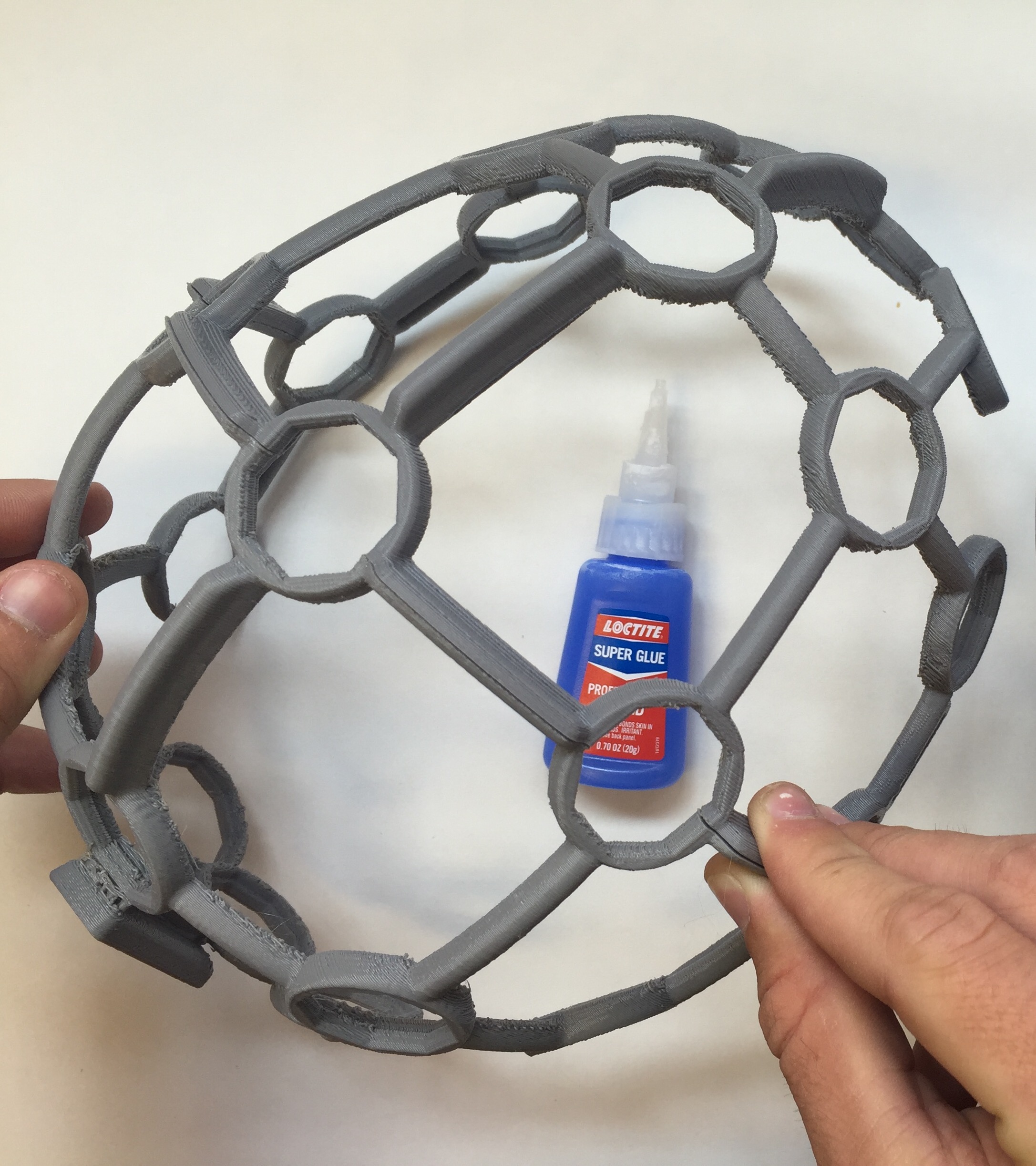
Glue the FRAME together
Carefully, glue the FRAME_FRONT and FRAME_BACK together with your Cyanoacrylate super glue. The best way to do this is to place both halves of the frame on a level surface and carefully bring them together. Be sure to be precise; it's VERY difficult to pull the pieces apart once you've put them together.
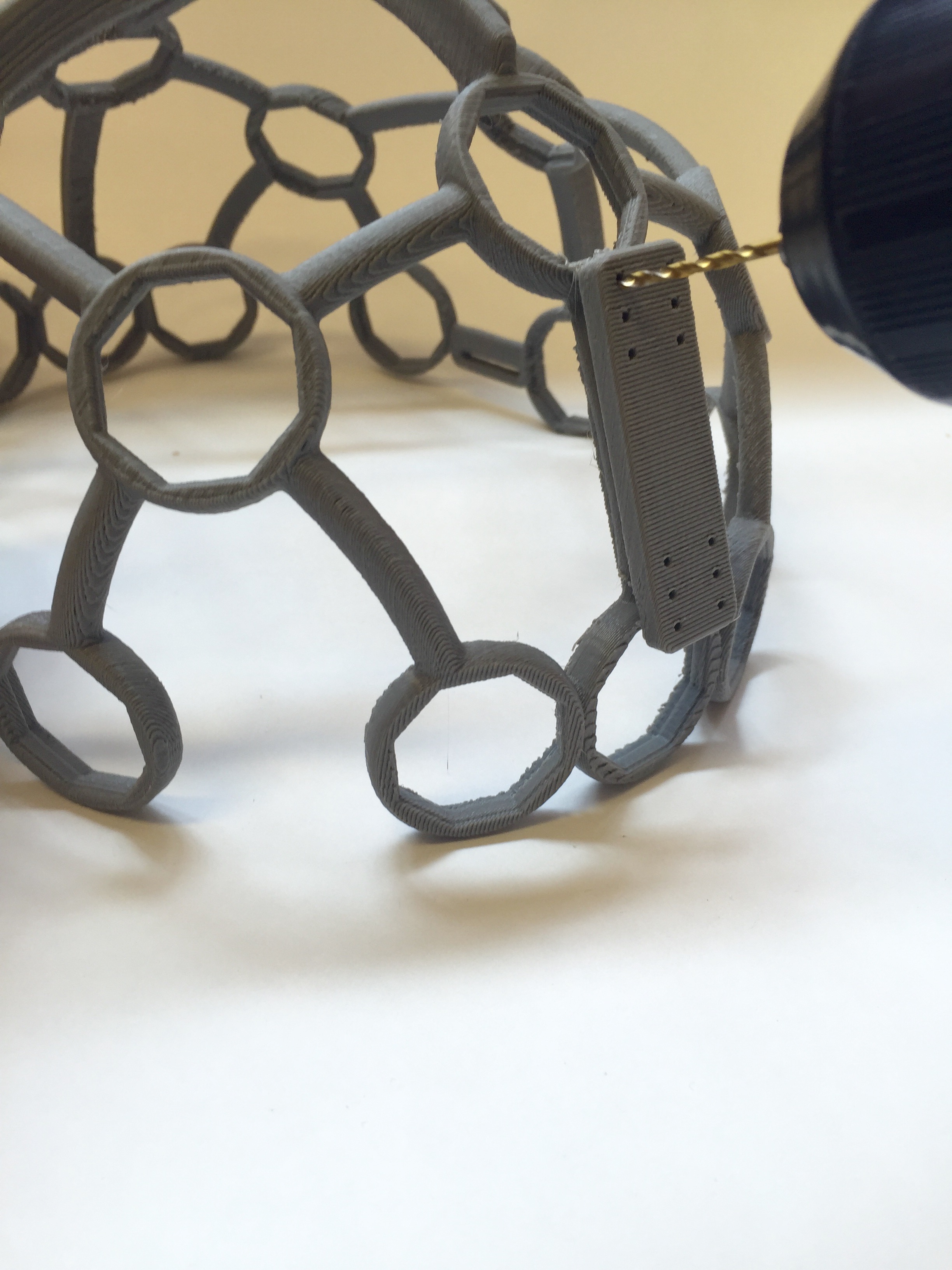
Mount the OpenBCI BOARD_HOLDER
First, use a 1/16" drillbit to expand the holes on the Ultracortex frame. This will make it easier to screw the BOARD_HOLDER on the frame.
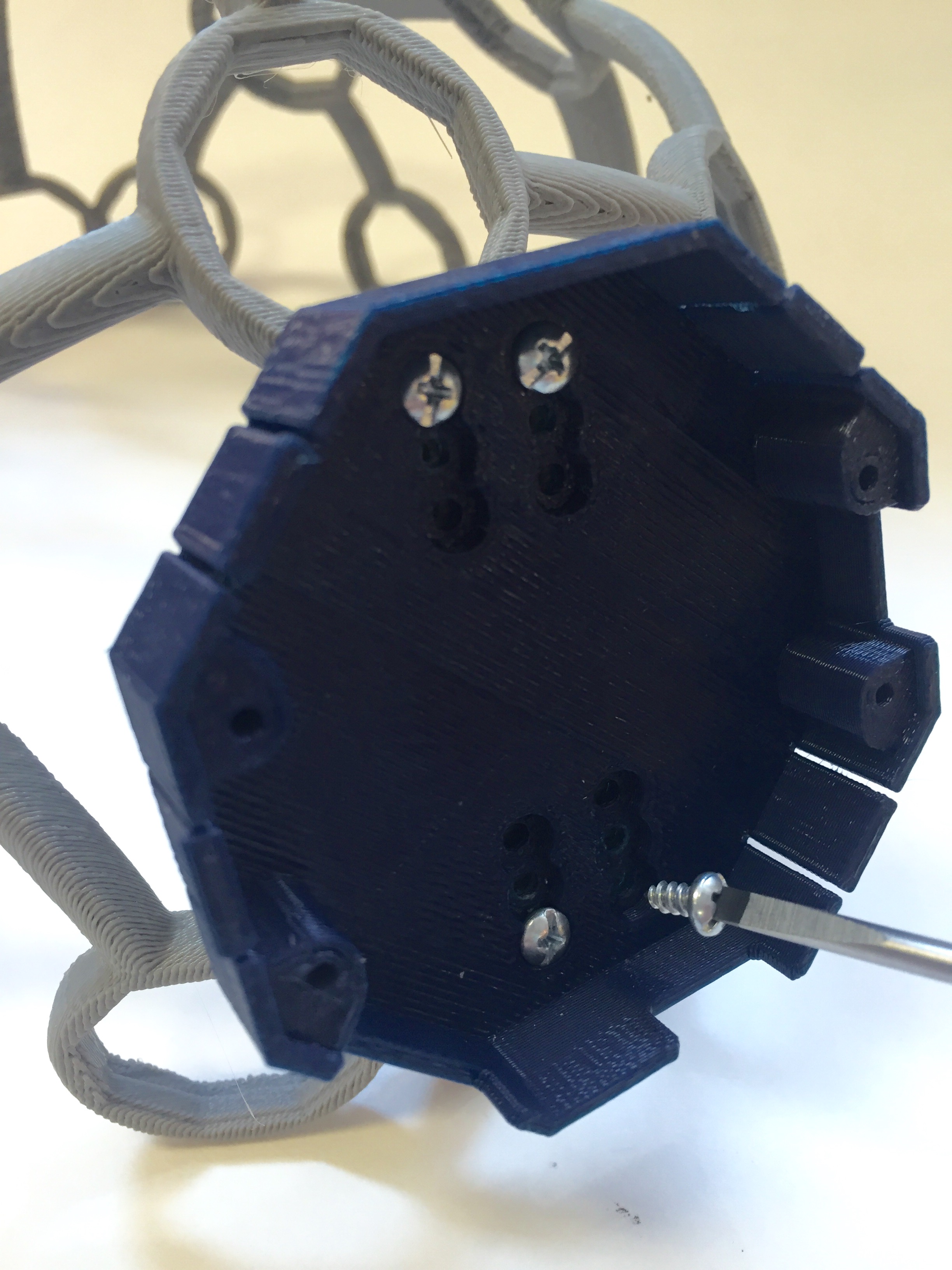
Use four #4 Drive Screws to mount the BOARD_HOLDER to the FRAME. Make sure that the orientation of the BOARD_HOLDER matches that of the pictures below:
Assemble the Comfort Nodes
In order to fit the OCTANUT pieces into the frame, you will need the Comfort Nodes in order to securely glue the OCTANUTs in place.
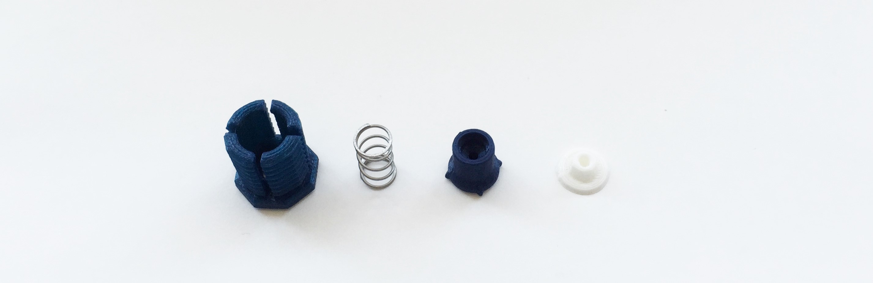
You will need the following pieces:
-OCTABOLT
-Strong Spring
-ELECTRODE_HOLDER
-Comfort insert
First, put the comfort insert into front of the ELECTRODE_HOLDER.
Next, insert the spring into the back of the ELECTRODE_HOLDER.
Then, slide the OCTABOLT over the top:
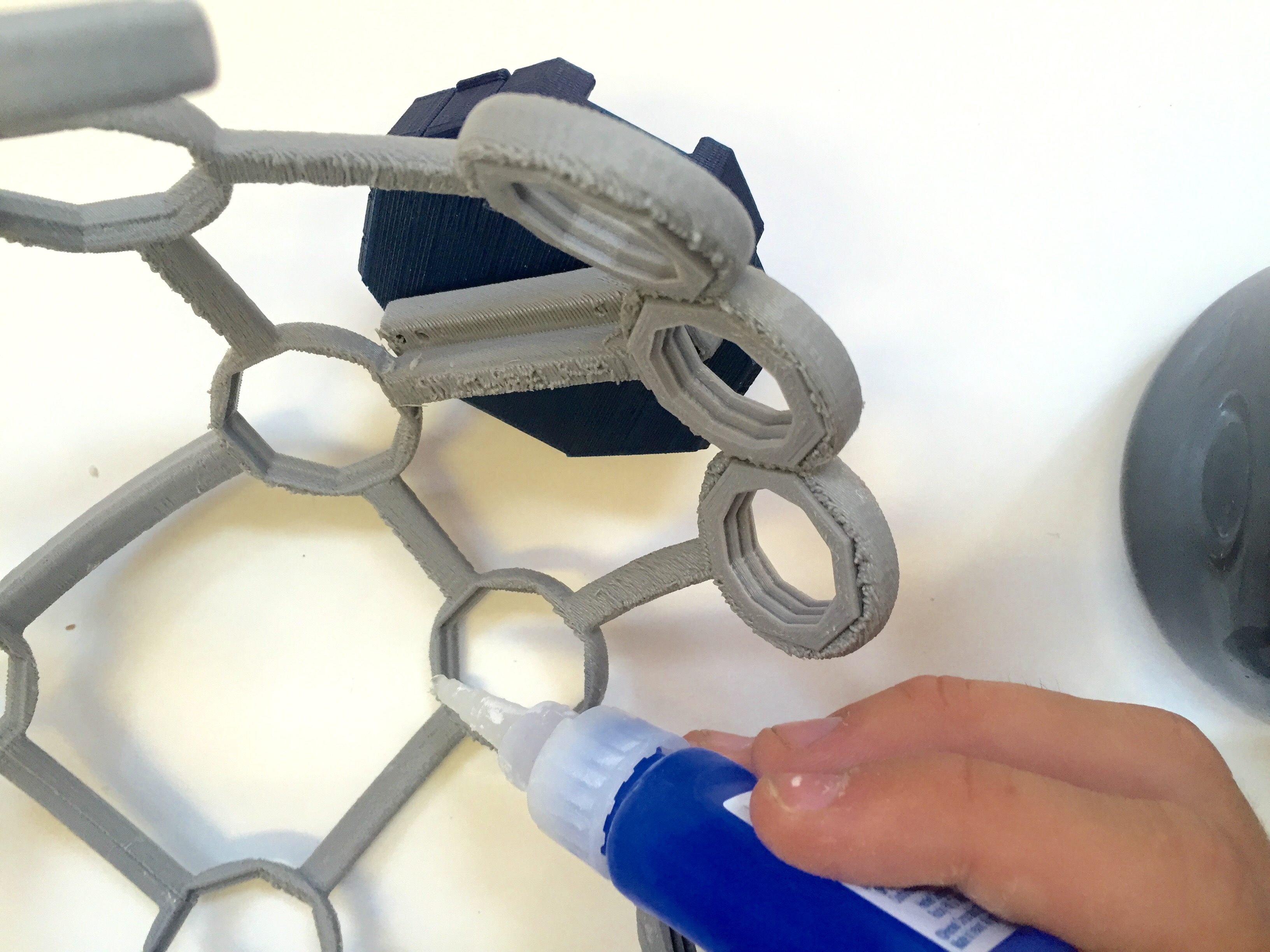
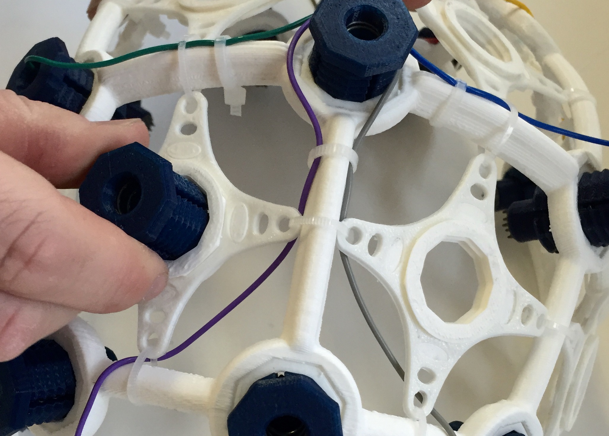
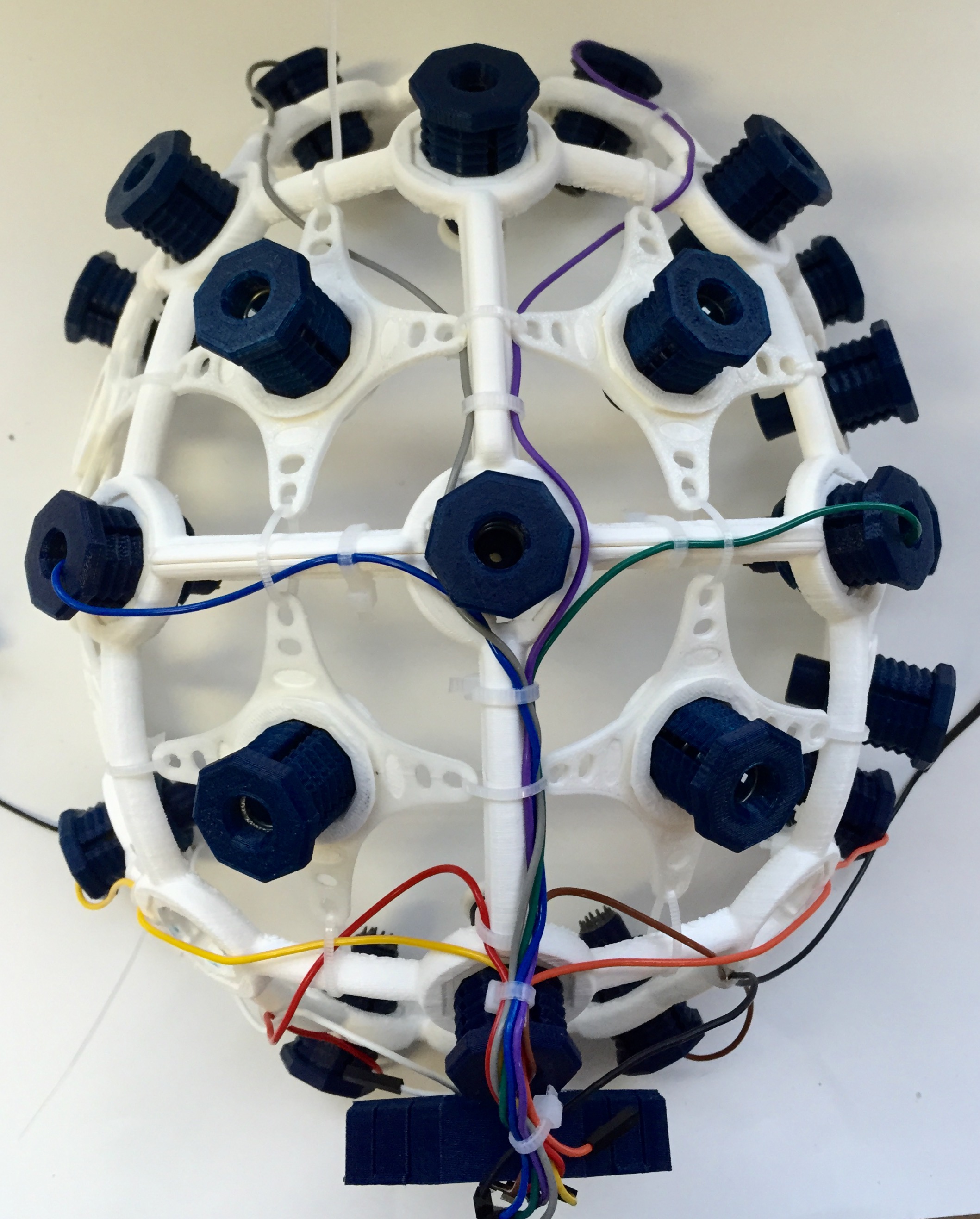
Insert OCTANUT pieces (x21) into frame
Note: Before glueing the OCTANUT into the frame ensure, that it fits properly into the frame without glue.
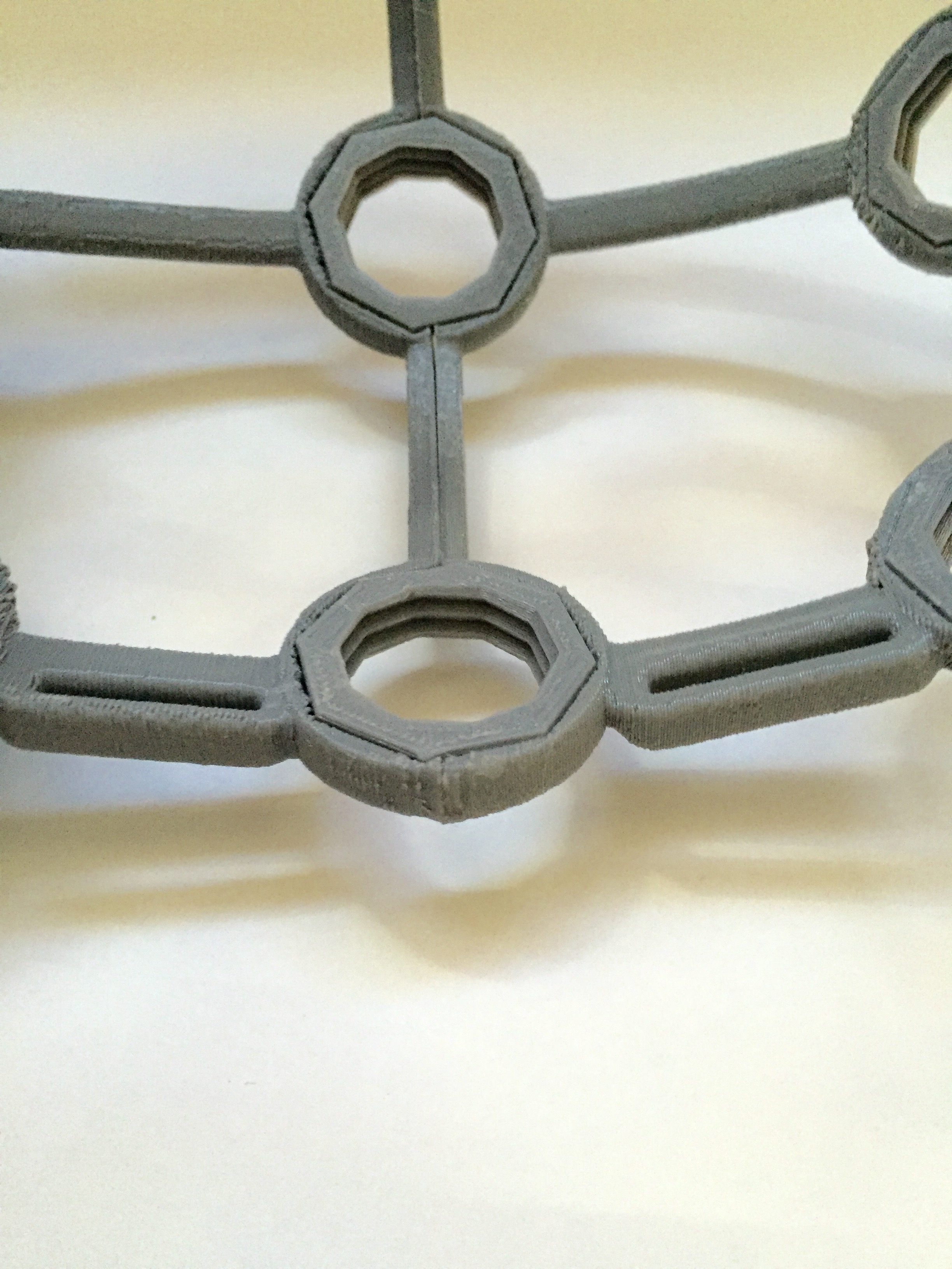
For each OCTANUT, line the inner rim of frame with glue. Then insert the OCTANUT so that it is flush with the frame.
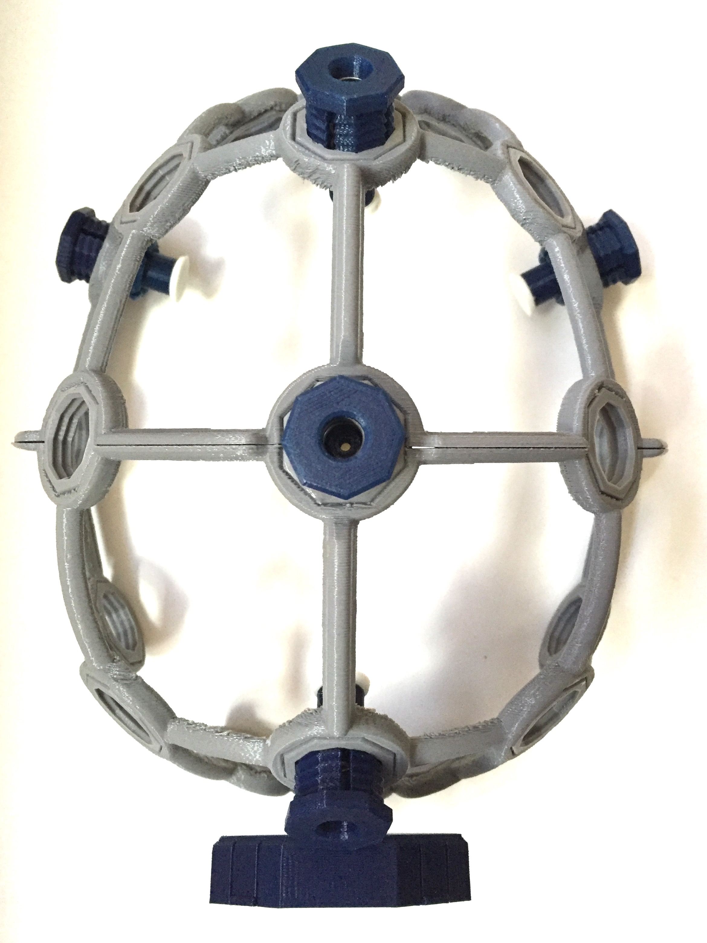
Your Ultracortex should now look like this:
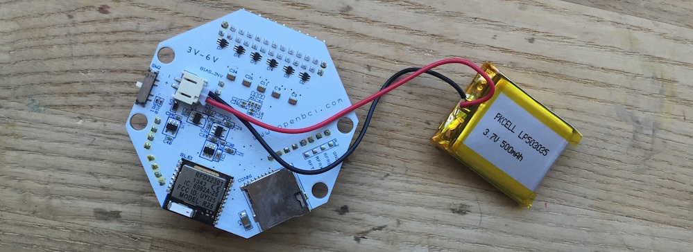
Embed OpenBCI into the Ultracortex
Connect your ~500 mAh lithium ion rechargeable batter to the back of your 32bit OpenBCI Board. Then fold the battery and its wires neatly behind the board before inserting the board into the BOARD_MOUNT. You can then use one of your #4 Drive Screws to secure the OpenBCI Board to the BOARD_MOUNT. Typically you don't need to use any #4 Drive Screws because the BOARD_COVER locks the OpenBCI Board in place, but in this case it's a good idea because you'll want to see where you're connecting your wires.
Identify electrode locations
Before creating your electrode mounts, it's a good idea to think about where you may want to place the electrodes on the Ultracortex FRAME. The placement of the electrode may affect how long you make the wire between the electrode and where the OpenBCI is mounted, at the back of the frame.
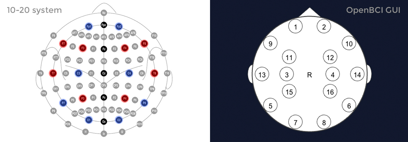
The Ultracortex node locations are based on the 10-20 system, which is the internationally accepted standard for electrode placement in the context of EEG.
The images below indicates the default 10-20 electrode locations that the OpenBCI Graphical User Interface expects. This application is great for viewing/recording your EEG and can be found in our OpenBCI_Processing repo. The blue nodes indicate the 8 default 10-20 locations (channels 1-8) of the 32bit Board. The red nodes indicate the default 10-20 locations of channels 9-16 when using the OpenBCI 16-channel R&D Kit.
For the remainder of this tutorial, the blue nodes on the 10-20 system diagram (channels 1-8 of the OpenBCI default settings) will be used. The channel to 10-20 system correlations are as follows:
- Channel 1(N1P) - Fp1
- Channel 2(N2P) - Fp2
- Channel 3(N3P) - C3
- Channel 4(N4P) - C4
- Channel 5(N5P) - P7
- Channel 6(N6P) - P8
- Channel 7(N7P) - O1
- Channel 8(N8P) - O2
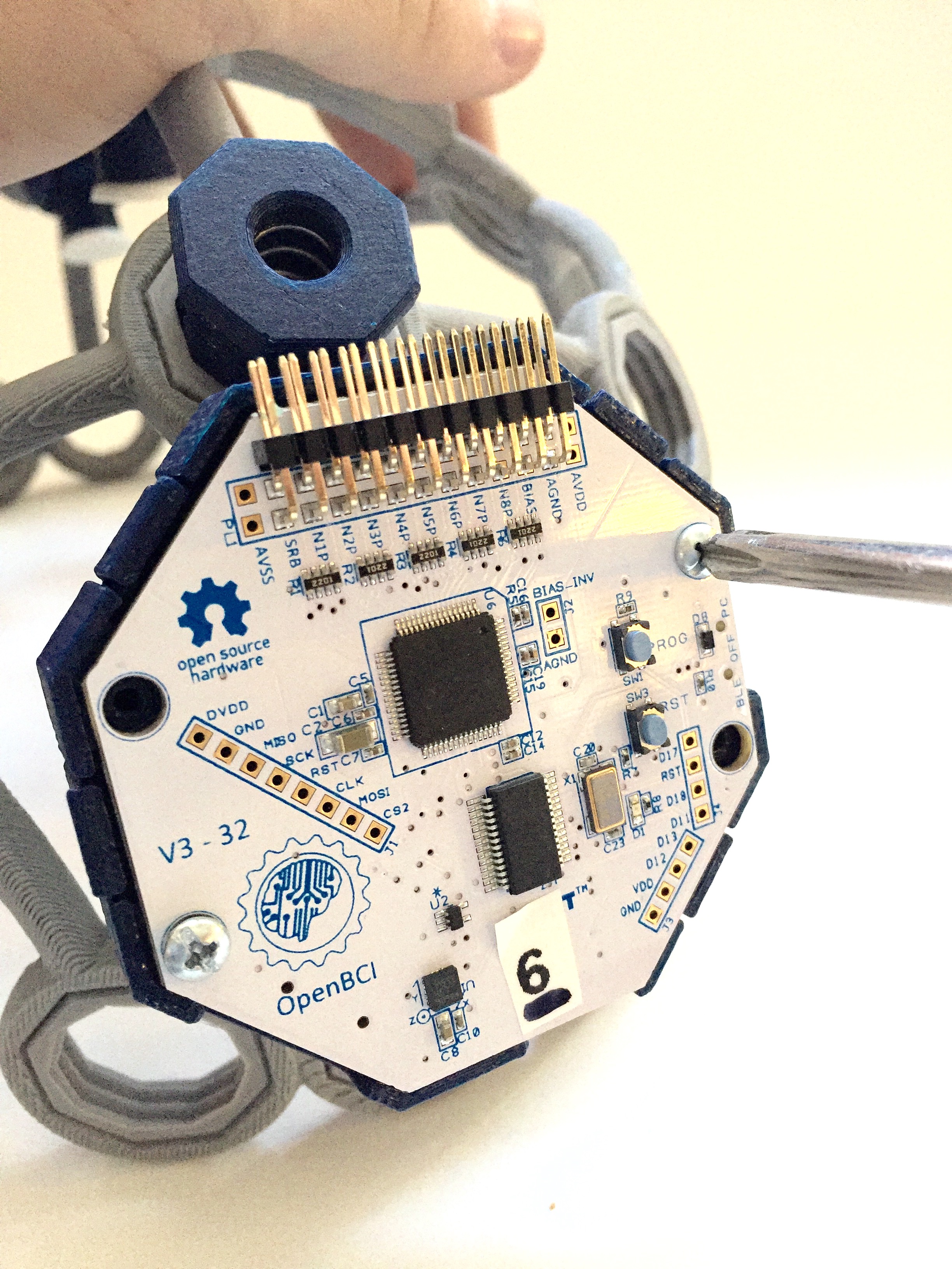
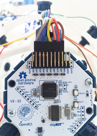
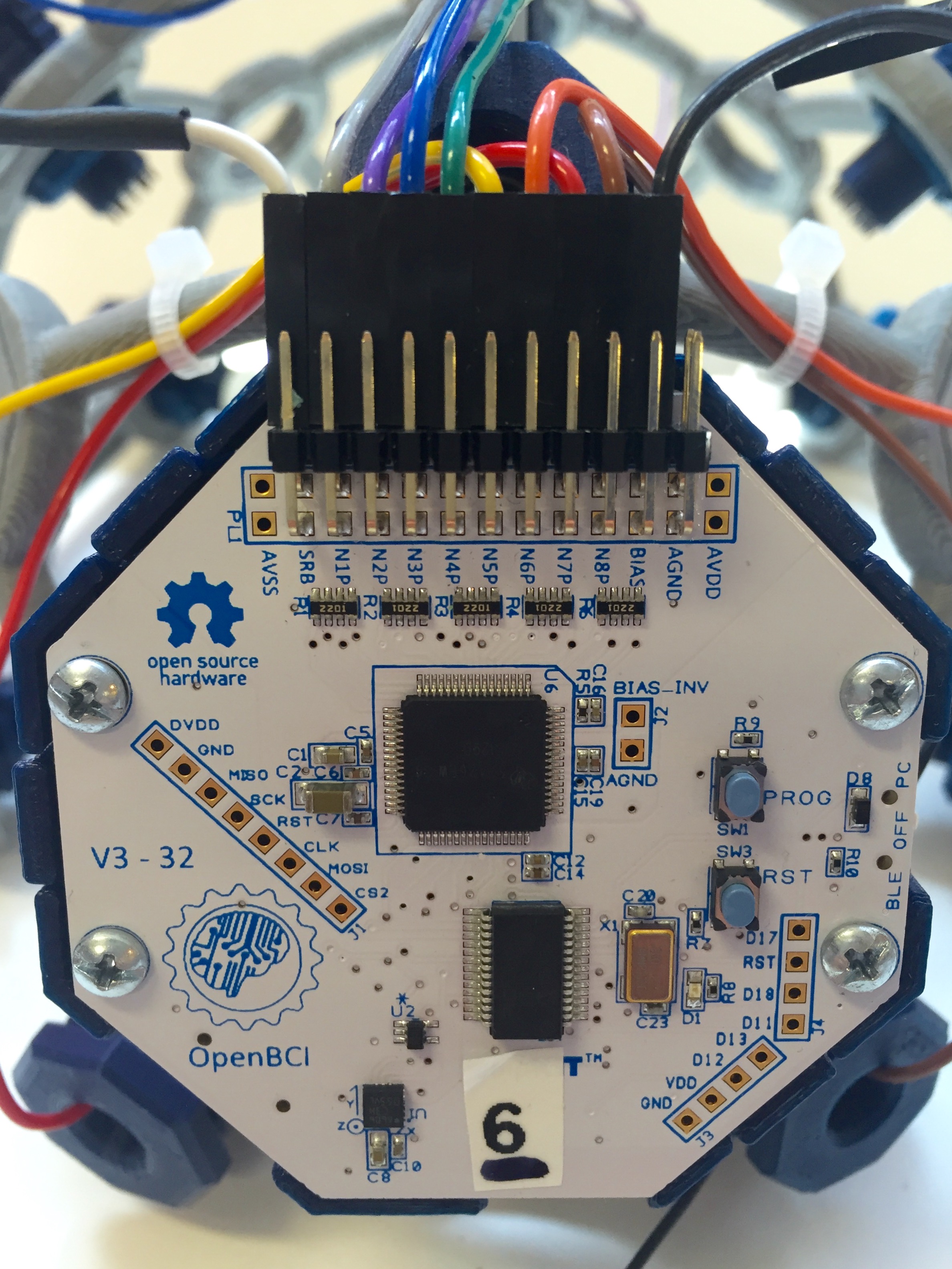
Connect wiring to OpenBCI
Before shortening any of your wires, connect the female header of each wire to the N pin of channels 1-8, as indicated in the image to the lower right. The N pins are the ones closer to the OpenBCI Board. By default, the OpenBCI Board references these 8 pins with the SRB 2 pin (the bottom SRB pin).
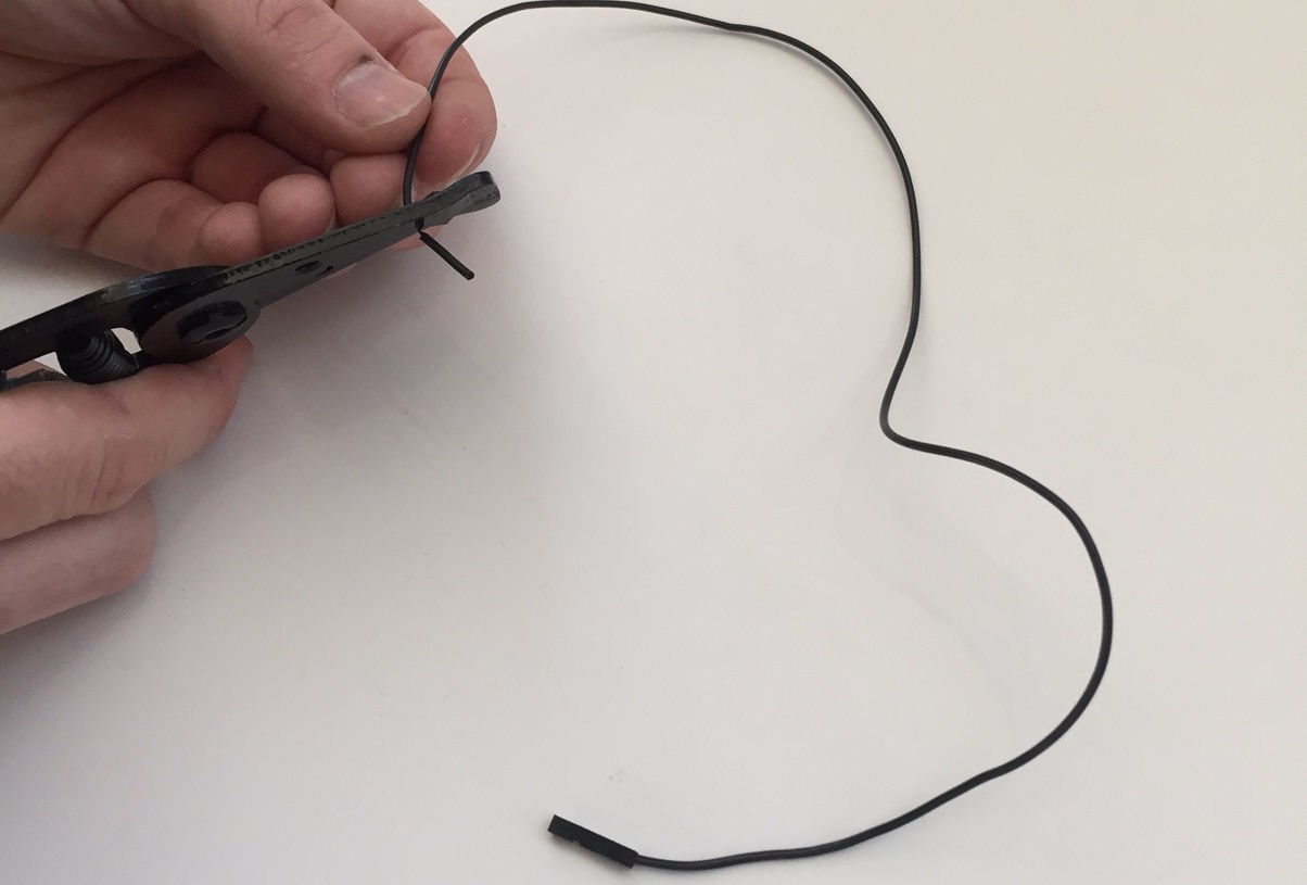
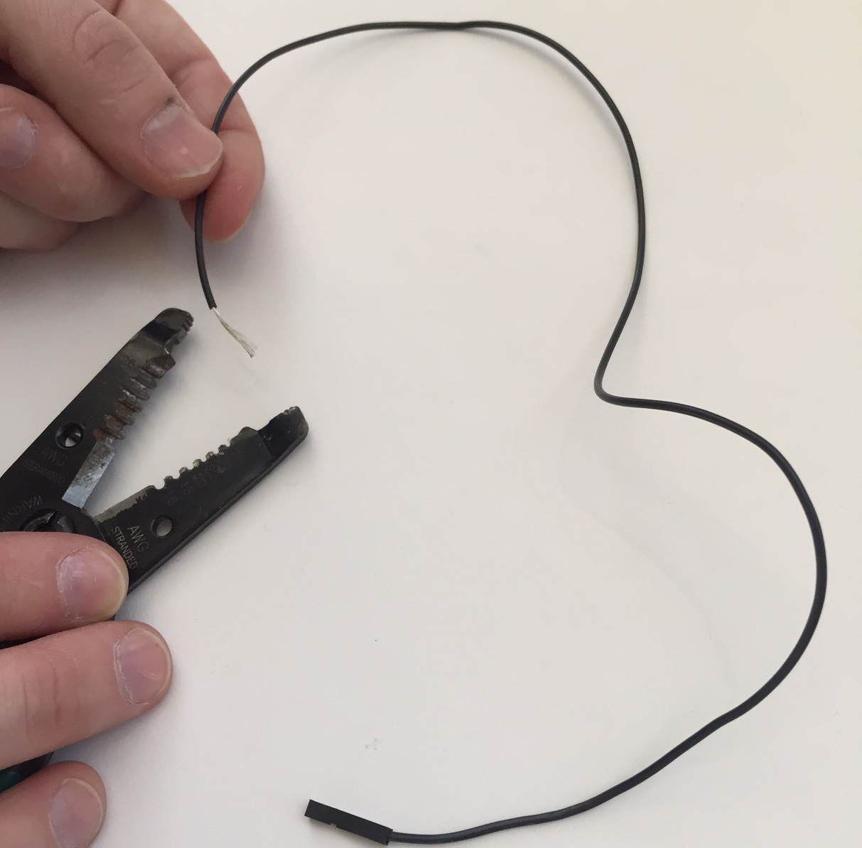
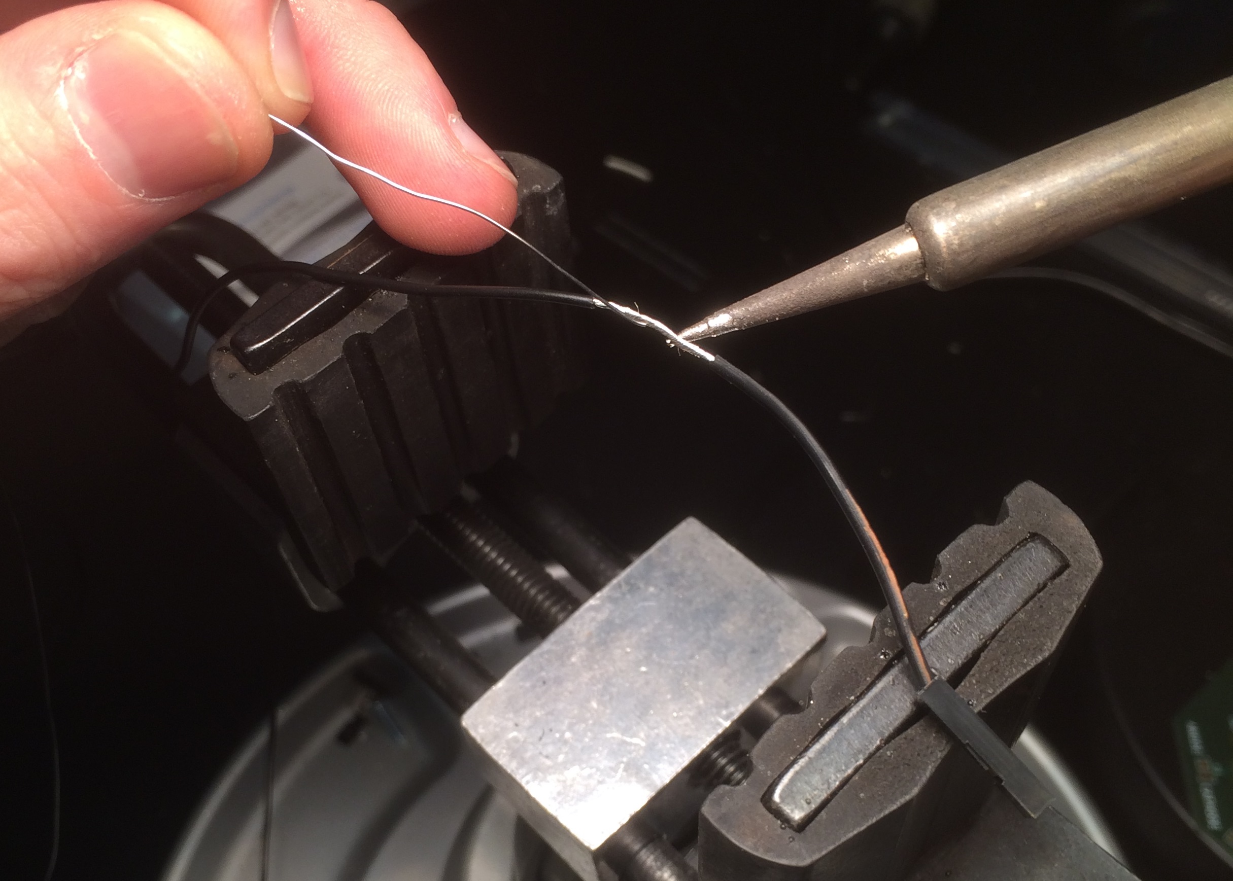
Measure, cut, and strip wires
For each wire, measure the distance between where it is connected to the OpenBCI Board and the node that it will terminate at on the Ultracortex frame. Give yourself 2-3 inches of slack (extra length), because you're going to strip the end of the wire, and you may want the extra slack to zip-tie/tape the wiring to the frame later on.
As mentioned above, if you're using the default OpenBCI electrode configuration, cut the wires so that they terminate at the following nodes:
- Channel 1(N1P) - Fp1
- Channel 2(N2P) - Fp2
- Channel 3(N3P) - C3
- Channel 4(N4P) - C4
- Channel 5(N5P) - P7
- Channel 6(N6P) - P8
- Channel 7(N7P) - O1
- Channel 8(N8P) - O2
After you're done measuring, cutting, and stripping your wires, disconnect them from the OpenBCI board. You will need the female header free so you can guide the springs and OCTANUT pieces into place in the following step. But remember which wire goes where!
Assemble electrode mounts (x8 or x16)
Note: repeat the following steps as many times as necessary, depending upon your OpenBCI setup. In general, using more electrodes will distribute the downward scalp pressure, increasing comfort. Additionally, to increase comfort you can create electrode units without electrodes and the wires to place at various nodes around the frame. This will also help to distribute pressure.
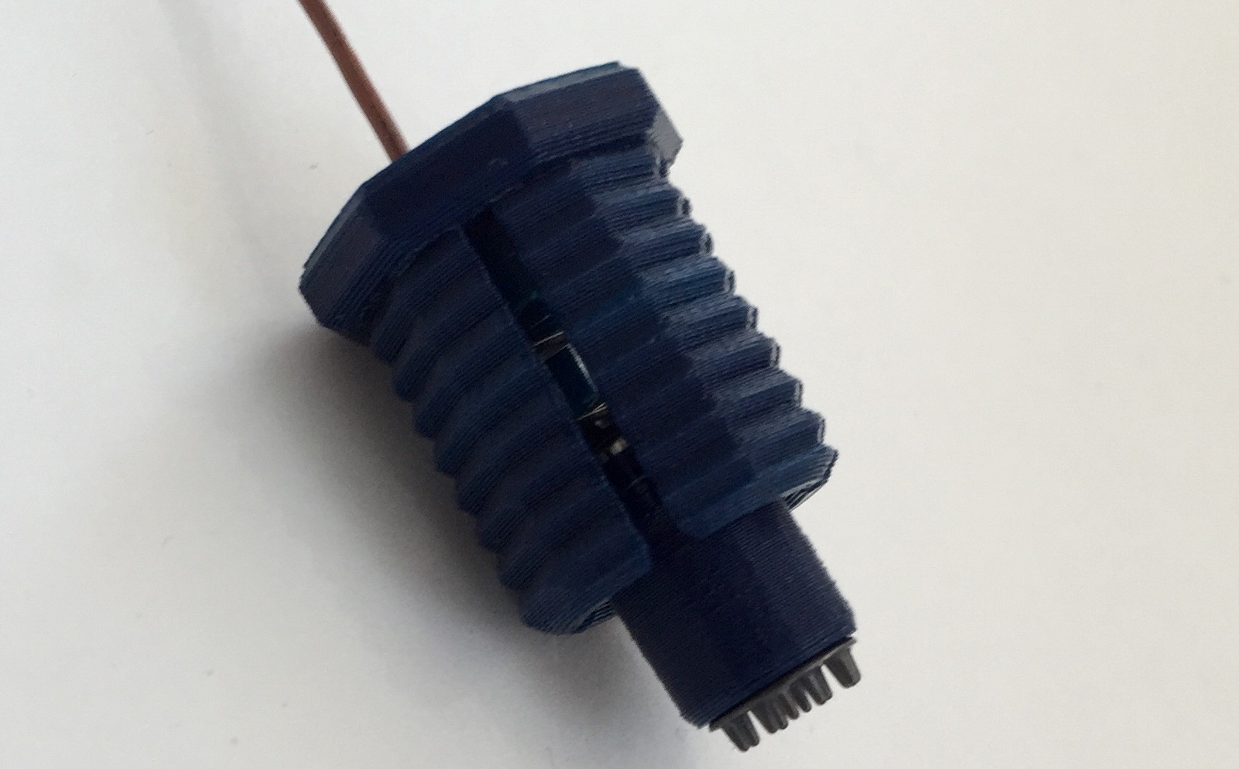
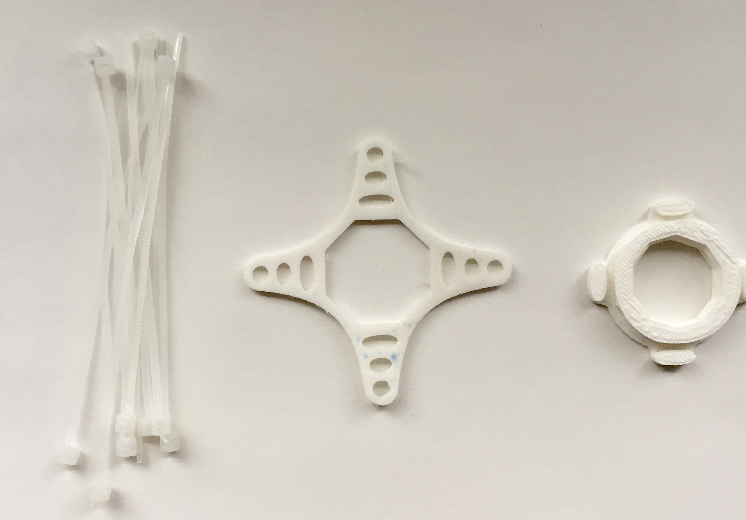
These are the pieces that comprise one full electrode unit:
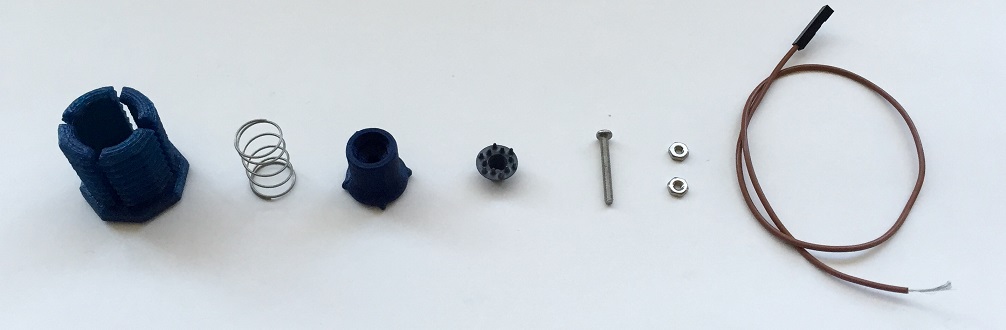
First, slide a Machine Screw (2-56 Thread, 3/4" Length) through the FRI electrode and guide it into the ELECTRODE_HOLDER. For channel 1 and channel 2 you may use flat electrodes since these elctrodes will be on your forehead where there is no hair.
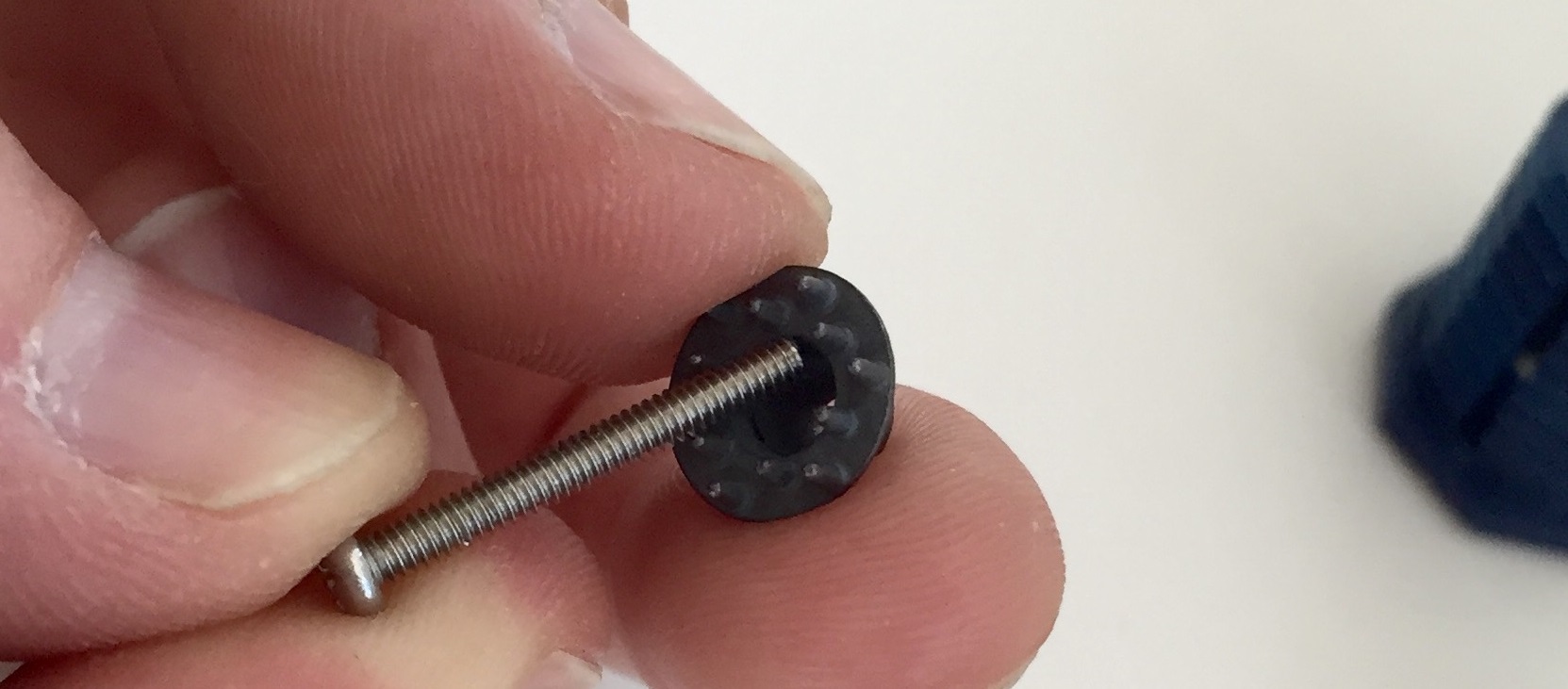
Then, slide the screw and electrode into the ELECTRODE_HOLDER
Next, twist a Hex Nut (2-56 Thread Size, 3/16" Wide, 1/16" High) onto the screw, securing the electrode to the holder.
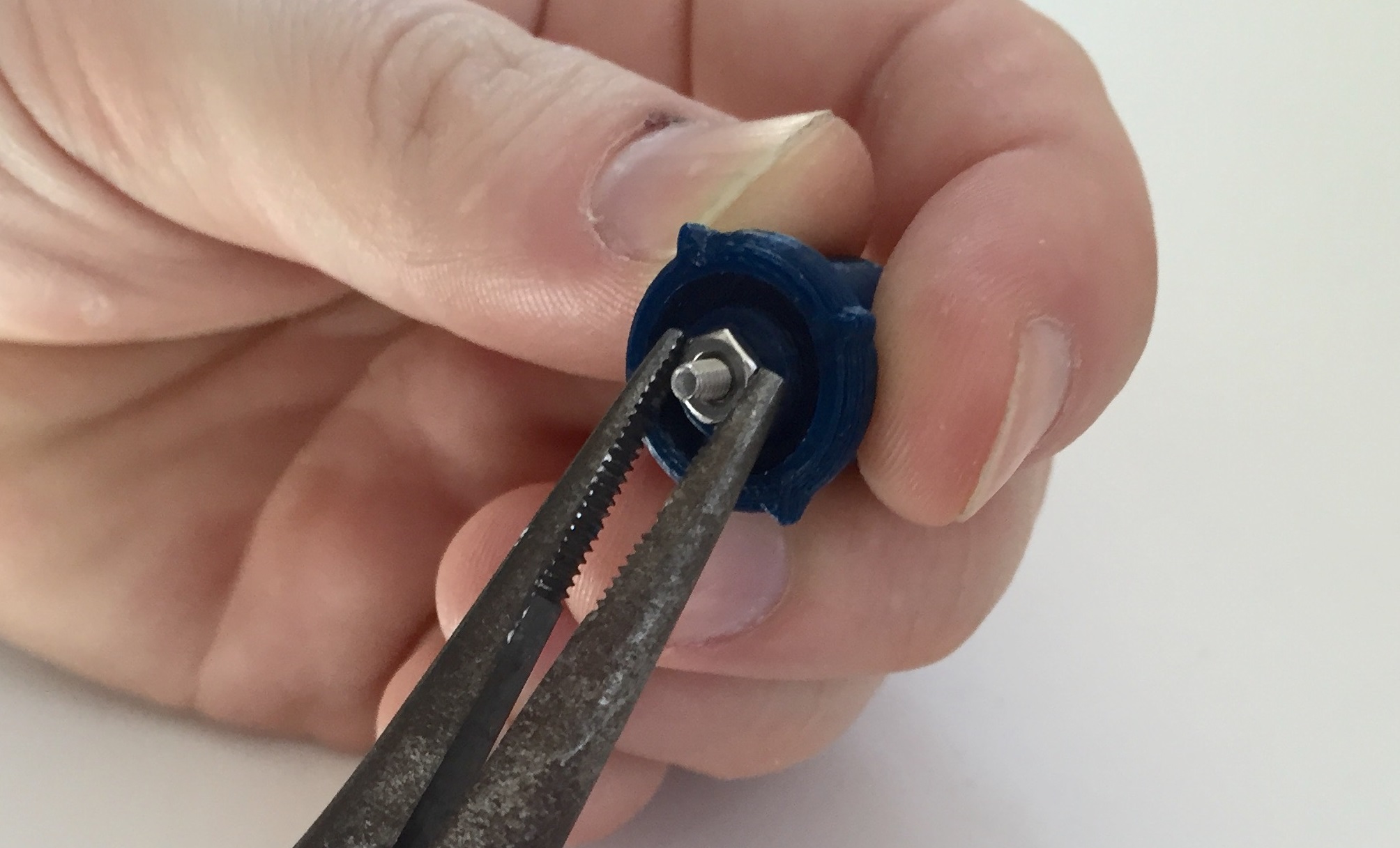
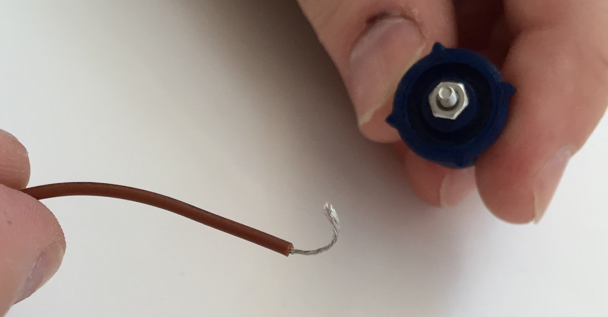
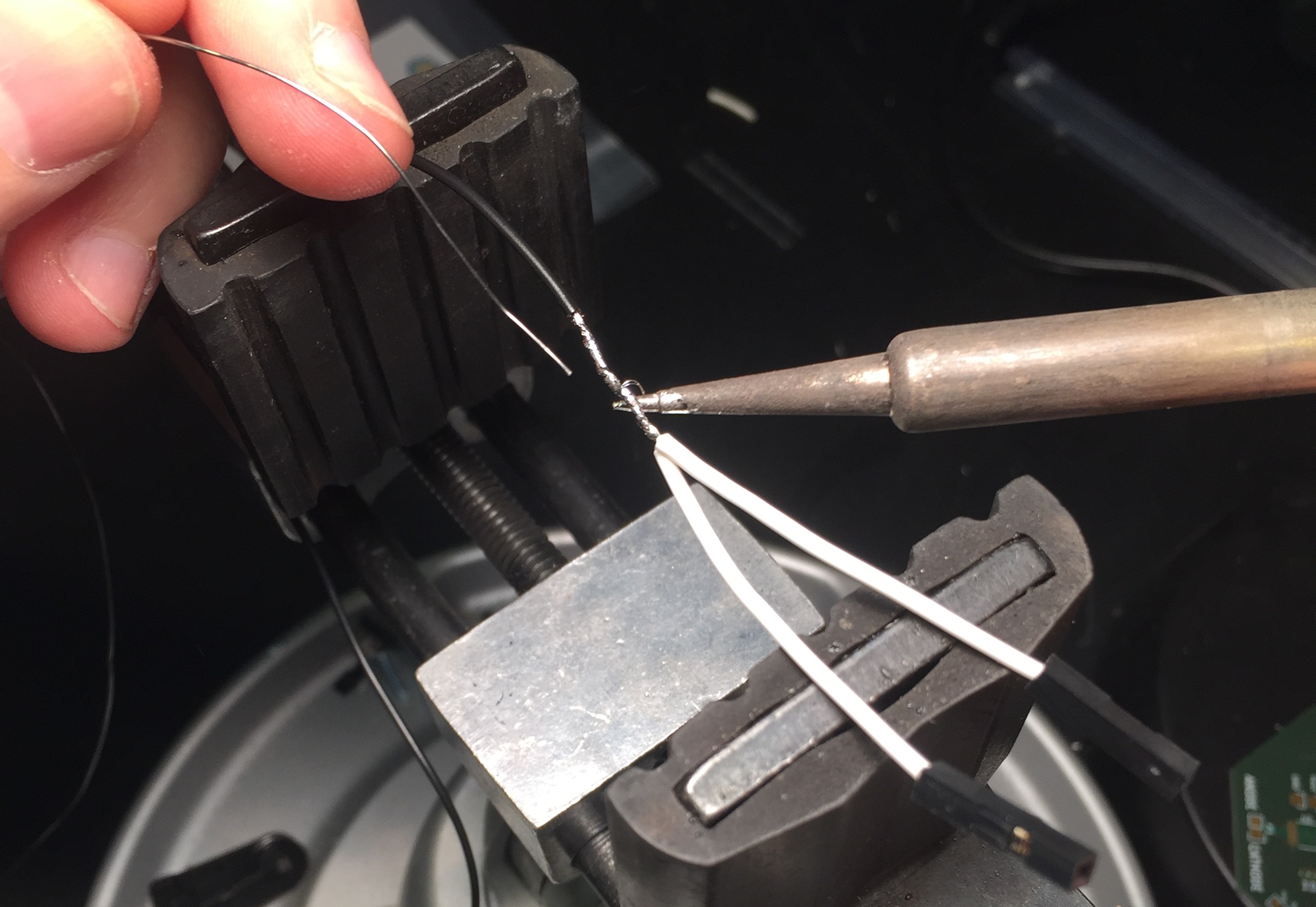
Next, twist the exposed metal of your wire so that it is tight and clean.
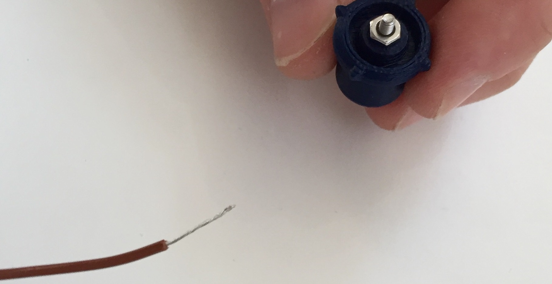
This part is a little bit tricky! Wrap the exposed metal of your wire once around the remaining thread of the screw. You can use your finger nail to pinch the wire down against the nut, while wrapping.
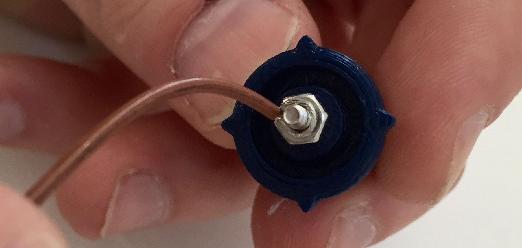
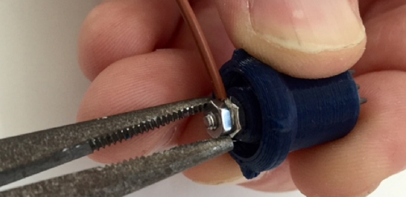
Then, twist your second Hex Nut onto the screw, securing the wire between the two nuts. You can use wire cutters to firmly screw the nut into place.
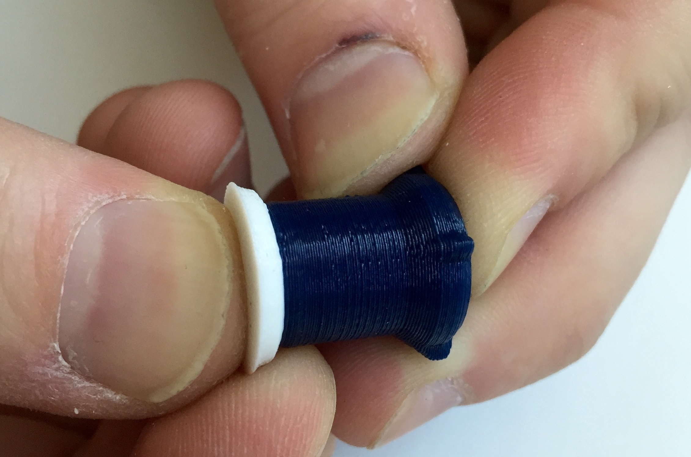
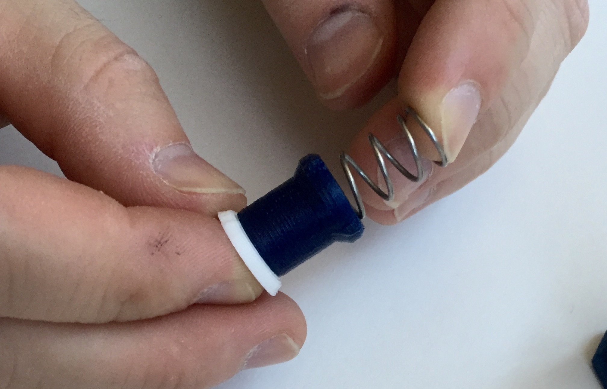
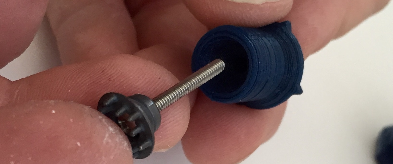
Slide a Suggested Spring 1 (aka "Weak Spring") and then the OCTABOLT around the wire as shown below.
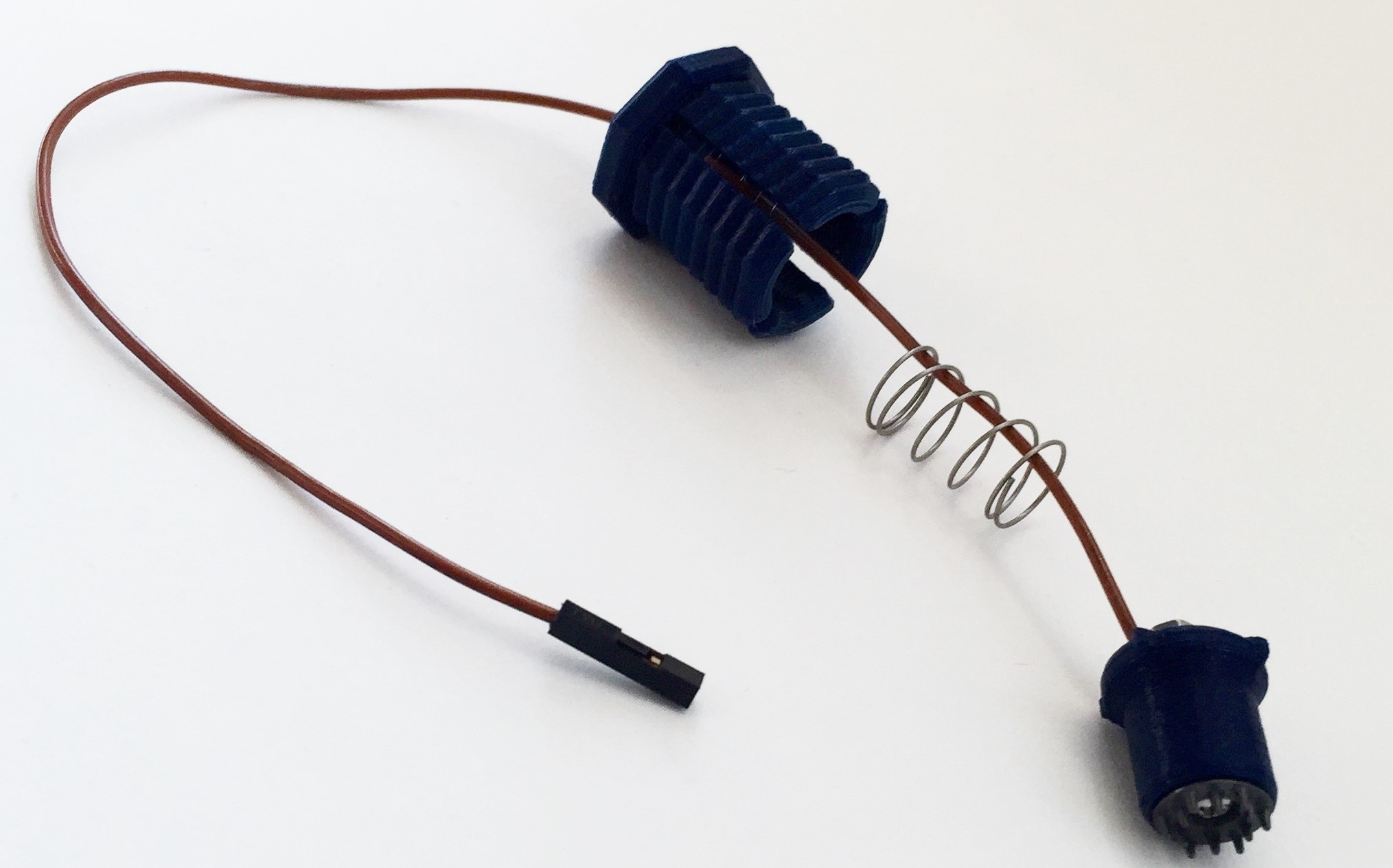
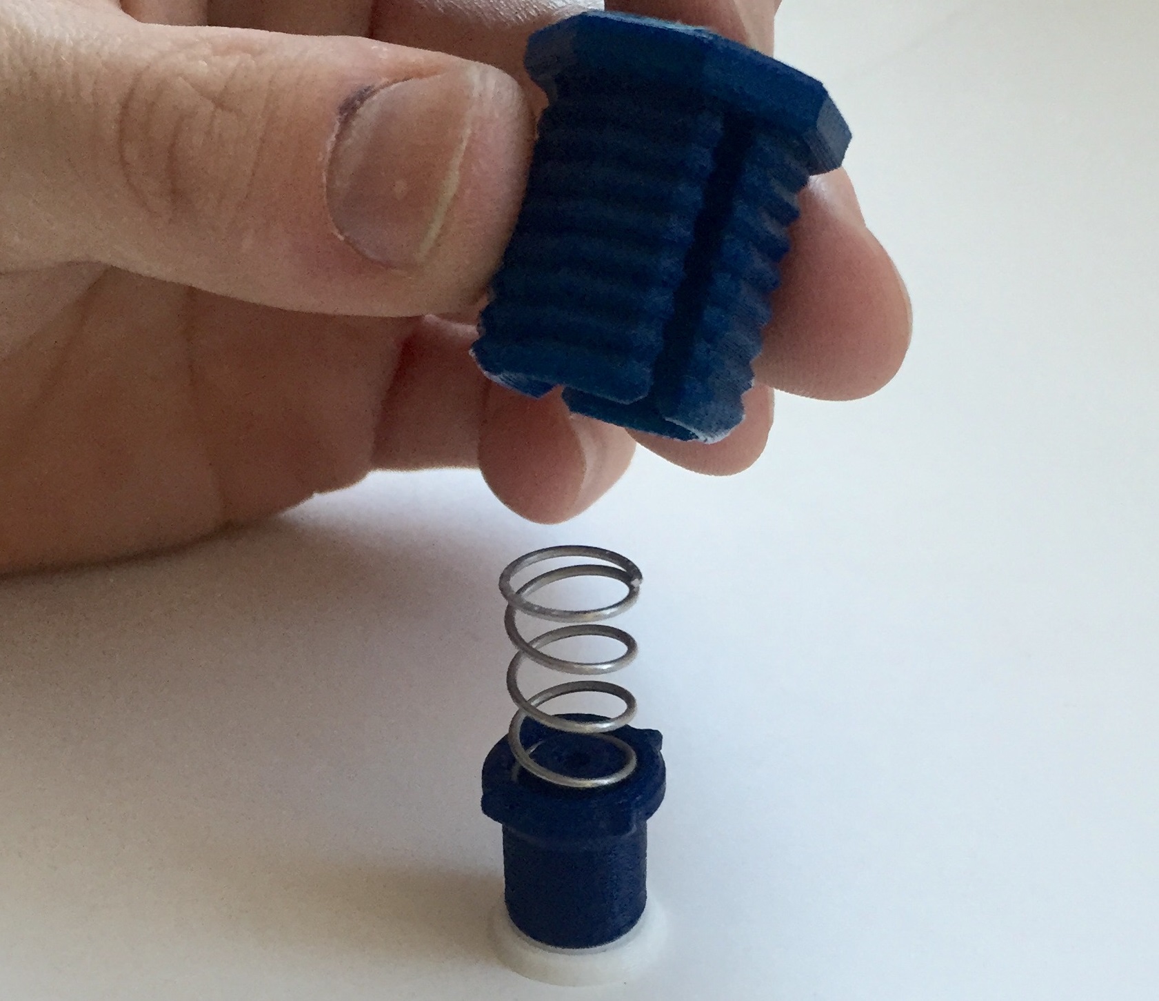
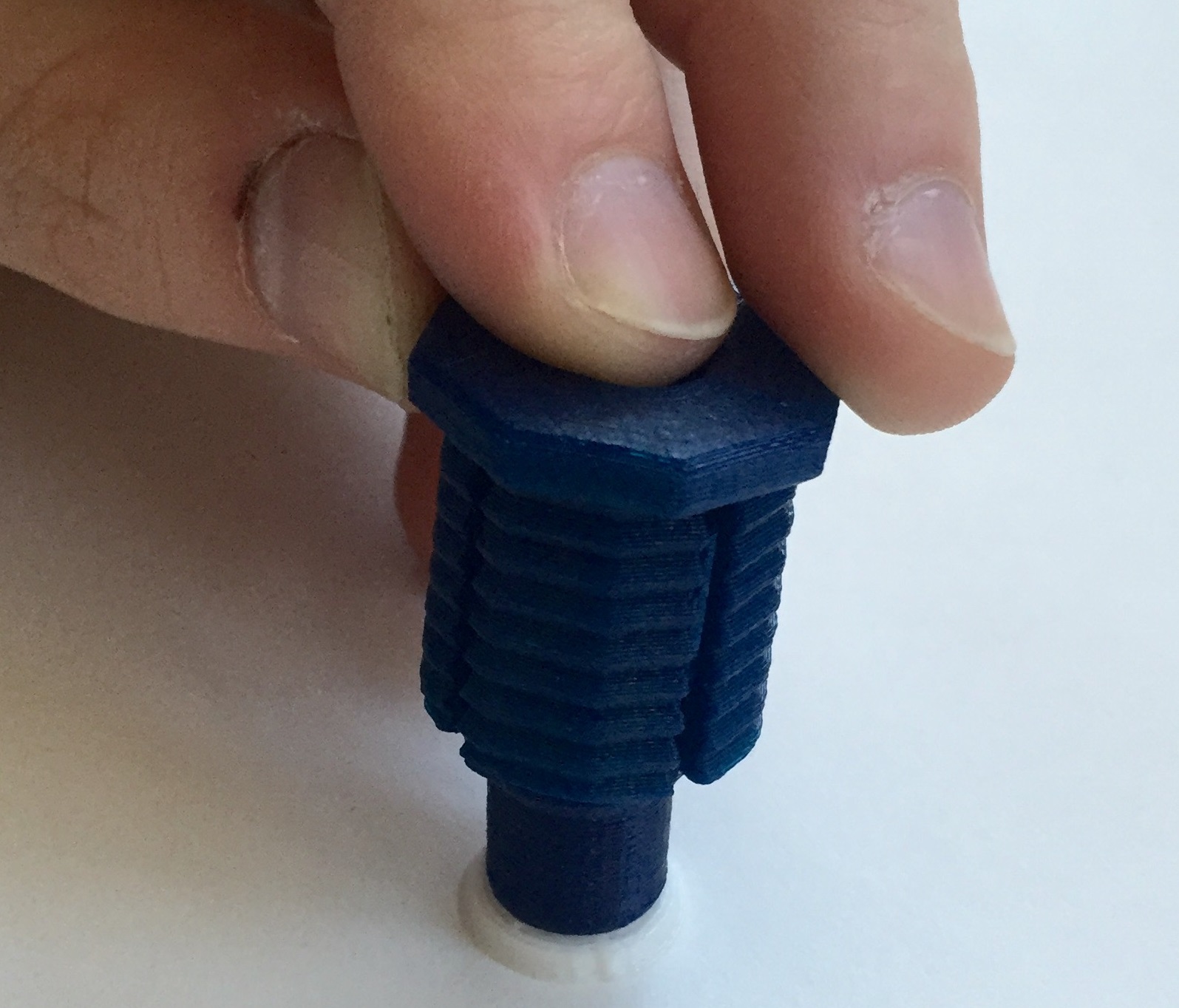
Snap the full electrode unit together, guiding the semi-spherical protrusions on the outside of the SPRING_CASING into the relief cuts of the OCTABOLT.
Voila! Spring-loaded electrode GIF!
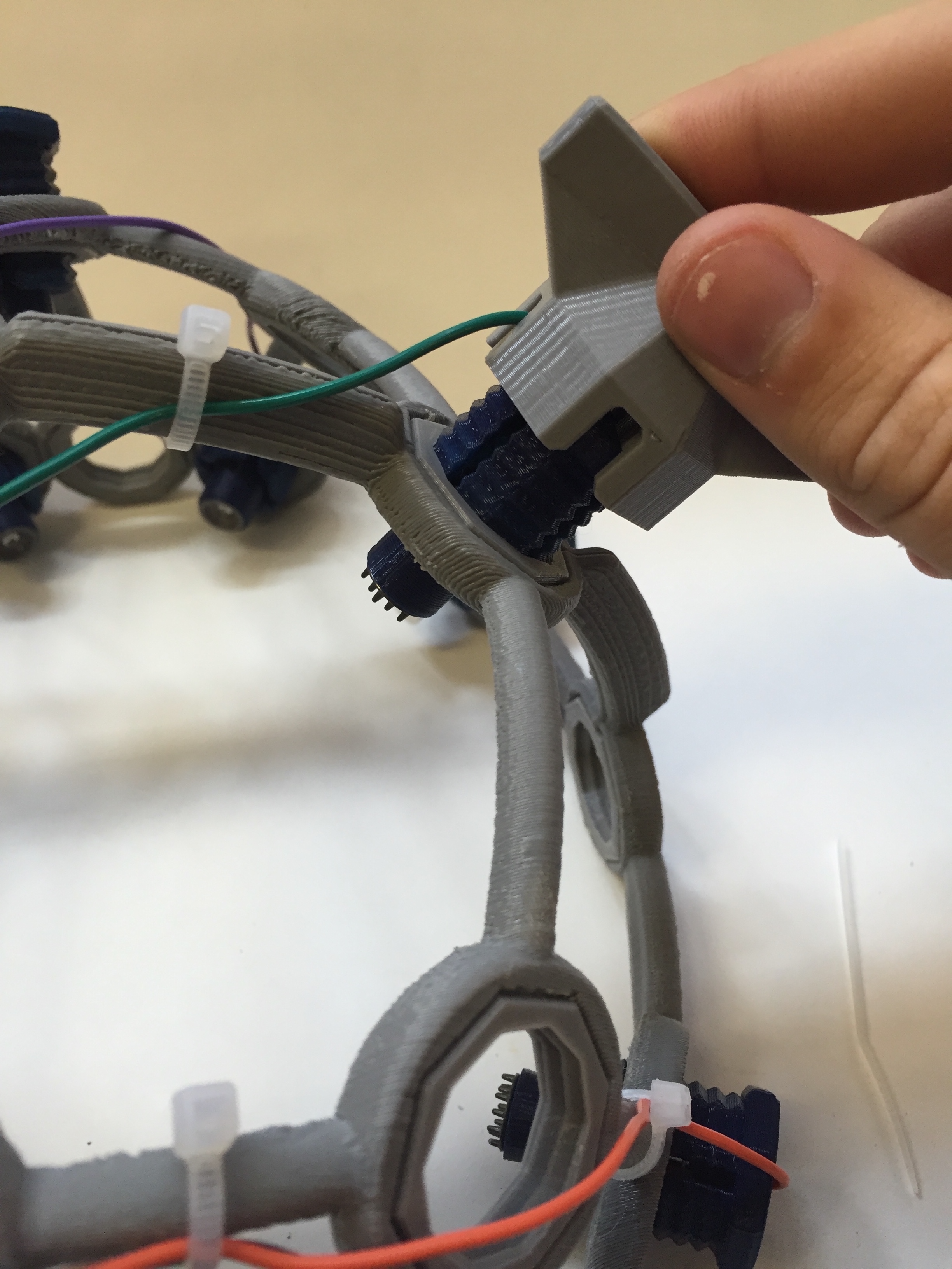
Insert electrode units into your Ultracortex
Once you've asesembled all of your electrode units, twist them into their respective Ultracortex frame nodes. If the parts are tough to twist into place by hand, use the OCTATOOL that comes with your kit as shown in the picture below. Over time the resistance between the OCTANUT and OCTABOLT will diminish, and the pieces will twist into place more easily.
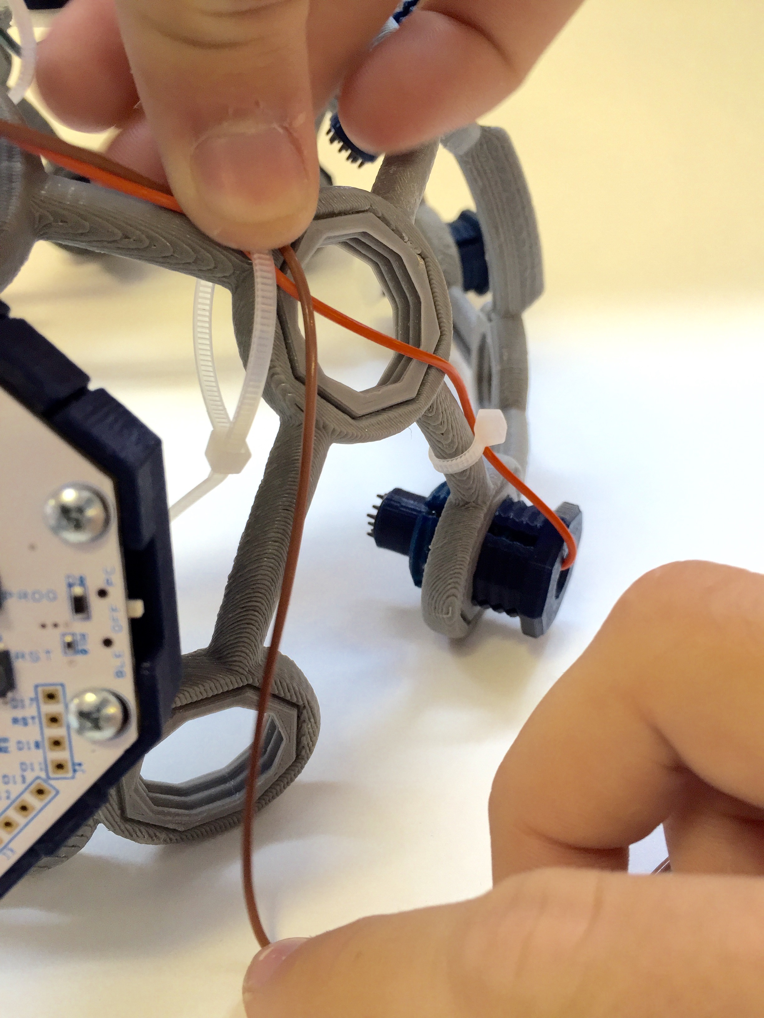
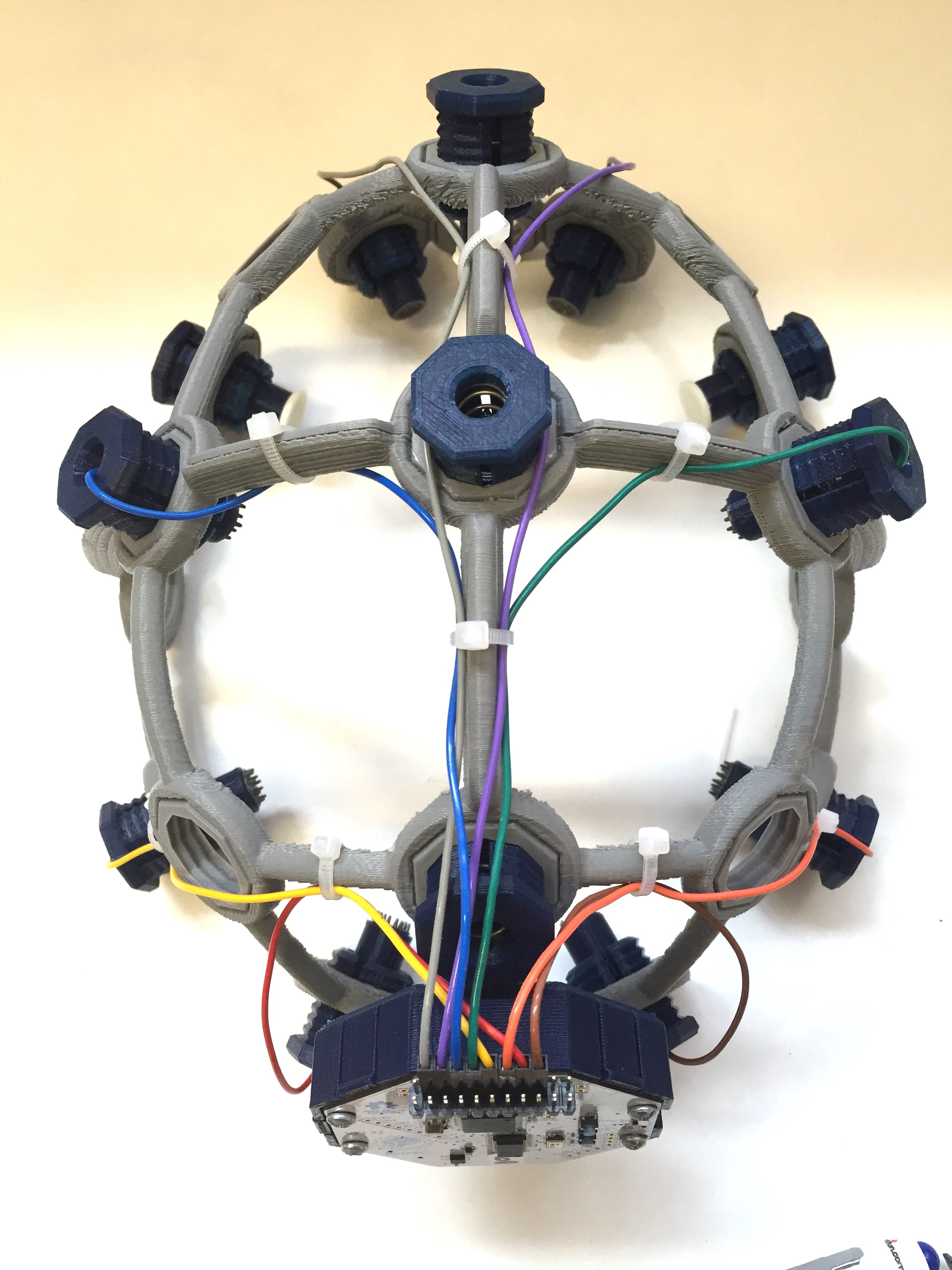
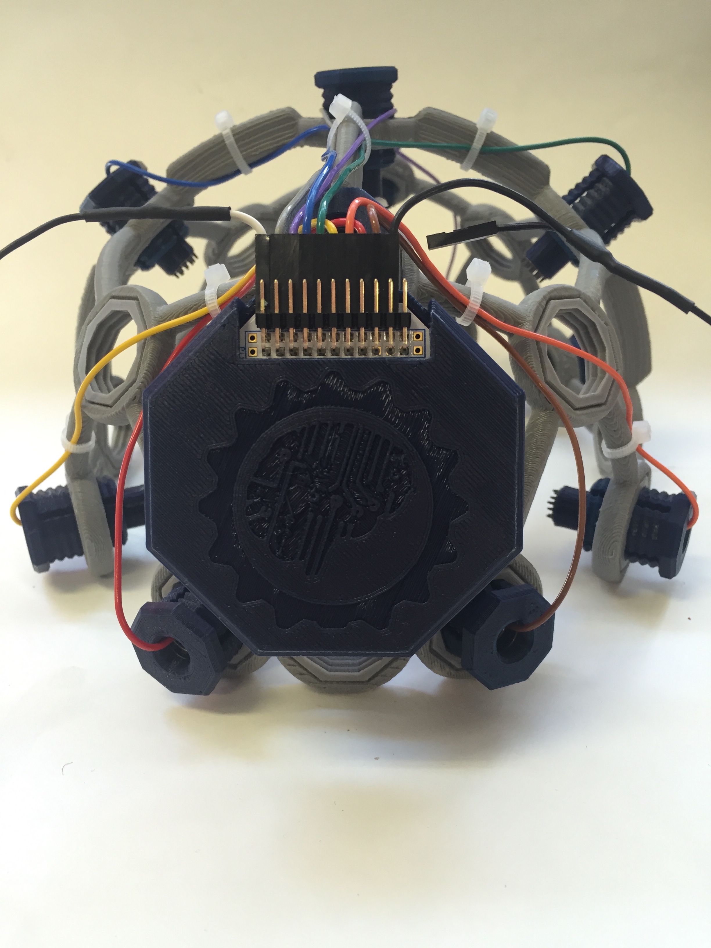
Reconnect wires to OpenBCI & connect ear clip electrodes (Reference & Ground)
Now that all of your electrode units are connected to your Ultracortex frame, reconnect the electrode wires to the OpenBCI board as detailed above. If you have some handy, you may want to use zip ties to secure the loose wiring to the Ultracortex frame. Later revisions of the headset will be designed to account for this. ;)
Next, connect two touch-proof adapter cables to SRB2 and bottom BIAS pin (white and black respectively in the image below). You can use the touch-proof adapter that comes with the OpenBCI 32bit Board or OpenBCI 16-channel R&D Kit. Then connect your ear clip electrodes to these touch-proof adapters. These ear clip electrodes serve as the reference and bias (ground with common-mode noise rejection) for your EEG system.
Alternatively, cut the earclip wire to about a foot long. Cut the touch-proof adapter wire to 2 inches long. Solder these two wires together, and shrink wrap them or wrap them in electrical tape.
For the 16 channel board, cut and solder two wires to the ear clip wire as shown:
Fasten the BOARD_COVER
Now clip your board cover into place. If you've soldered any of the header rows onto your OpenBCI board, you'll need to use the BOARD_COVER_ADVANCED, as seen in the picture below. Otherwise, you can use the BOARD_COVER_STANDARD with the OpenBCI logo.
Supernova Add-Ons
Parts
To add the QUADSTAR extensions to your Supernova, use the following parts:
3D Printed Parts
Note: the QUAD_STAR should be printed in a stretchy filament (like NinjaFlex or SemiFlex), as listed above in the Suggested Print Settings section.
- Quadstar (8X) -- .STL download link
- Octaring (8X) -- .STL download link
Non-3D Printed Parts
- Zip ties
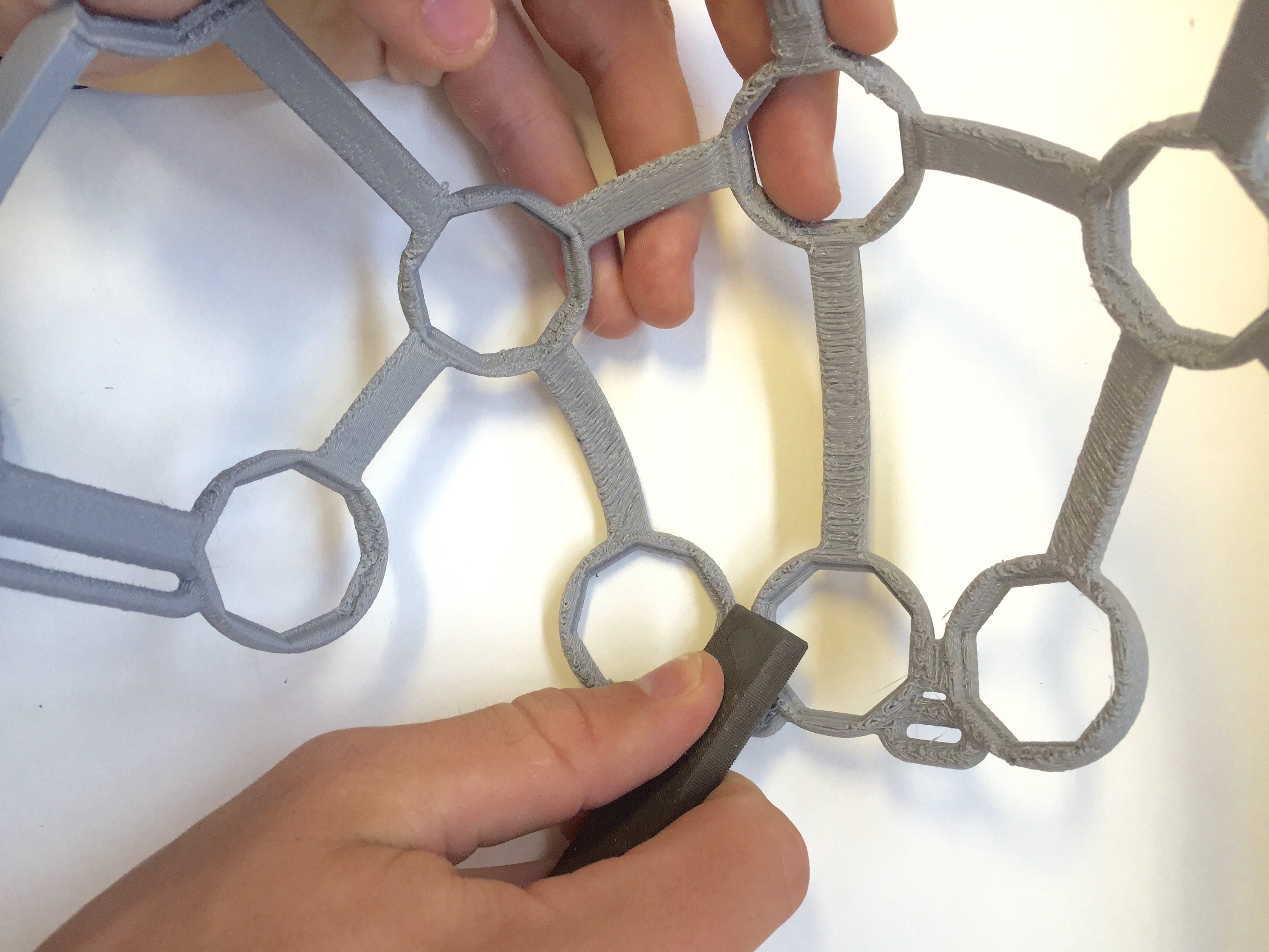
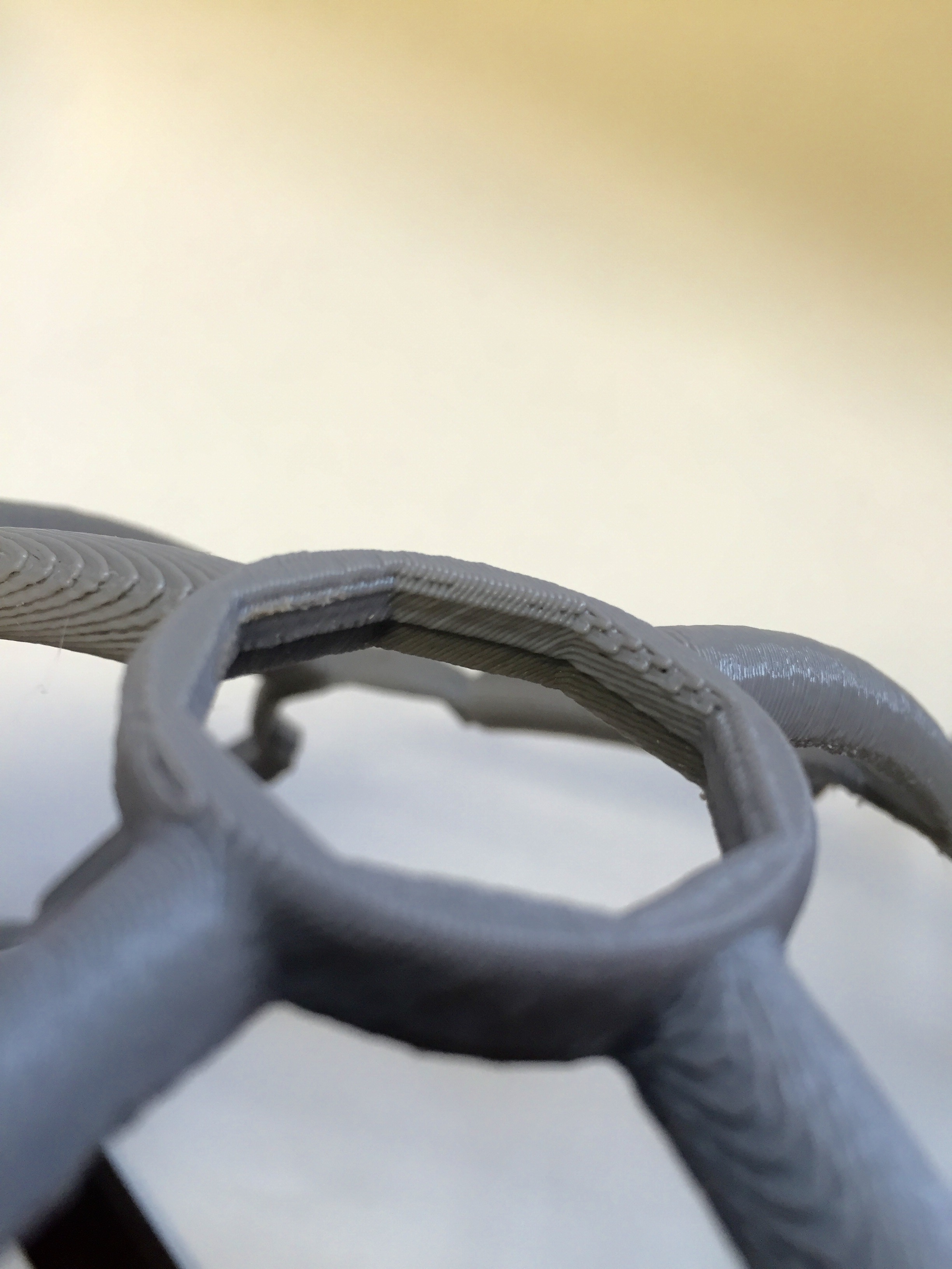
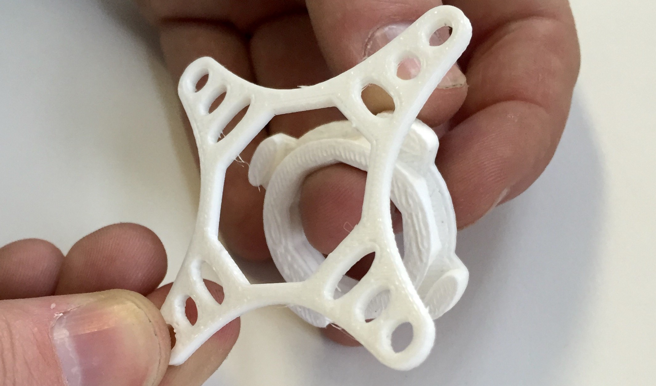
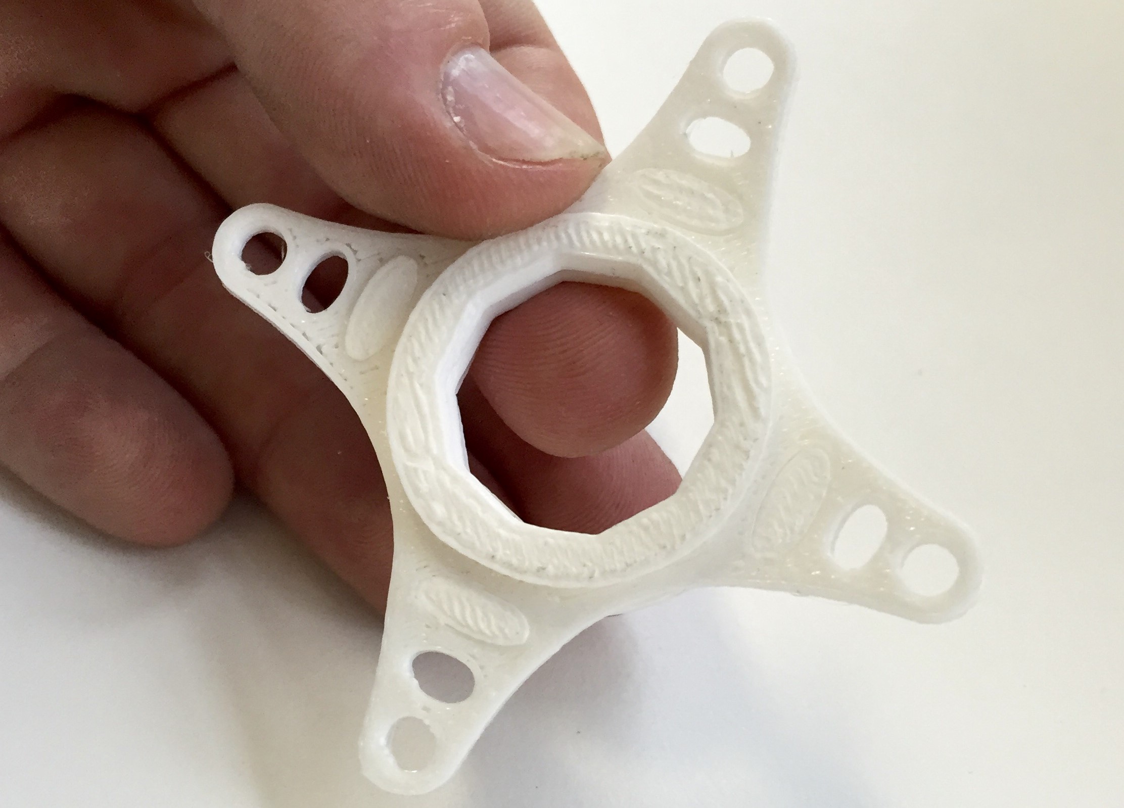
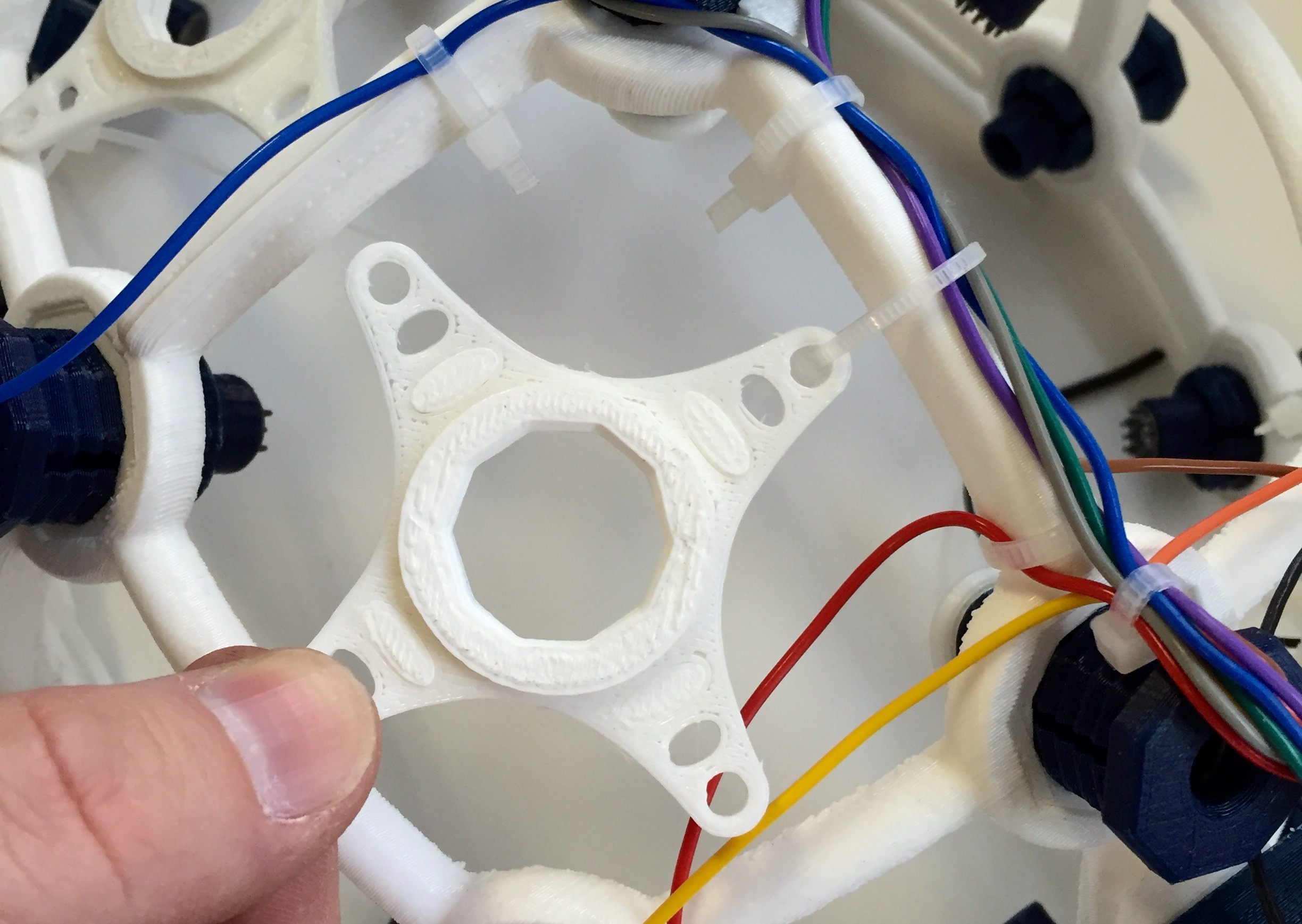
Stretch QUADSTAR over OCTARING
Take your QUADSTAR and stretch it so that it fits over the OCTARING
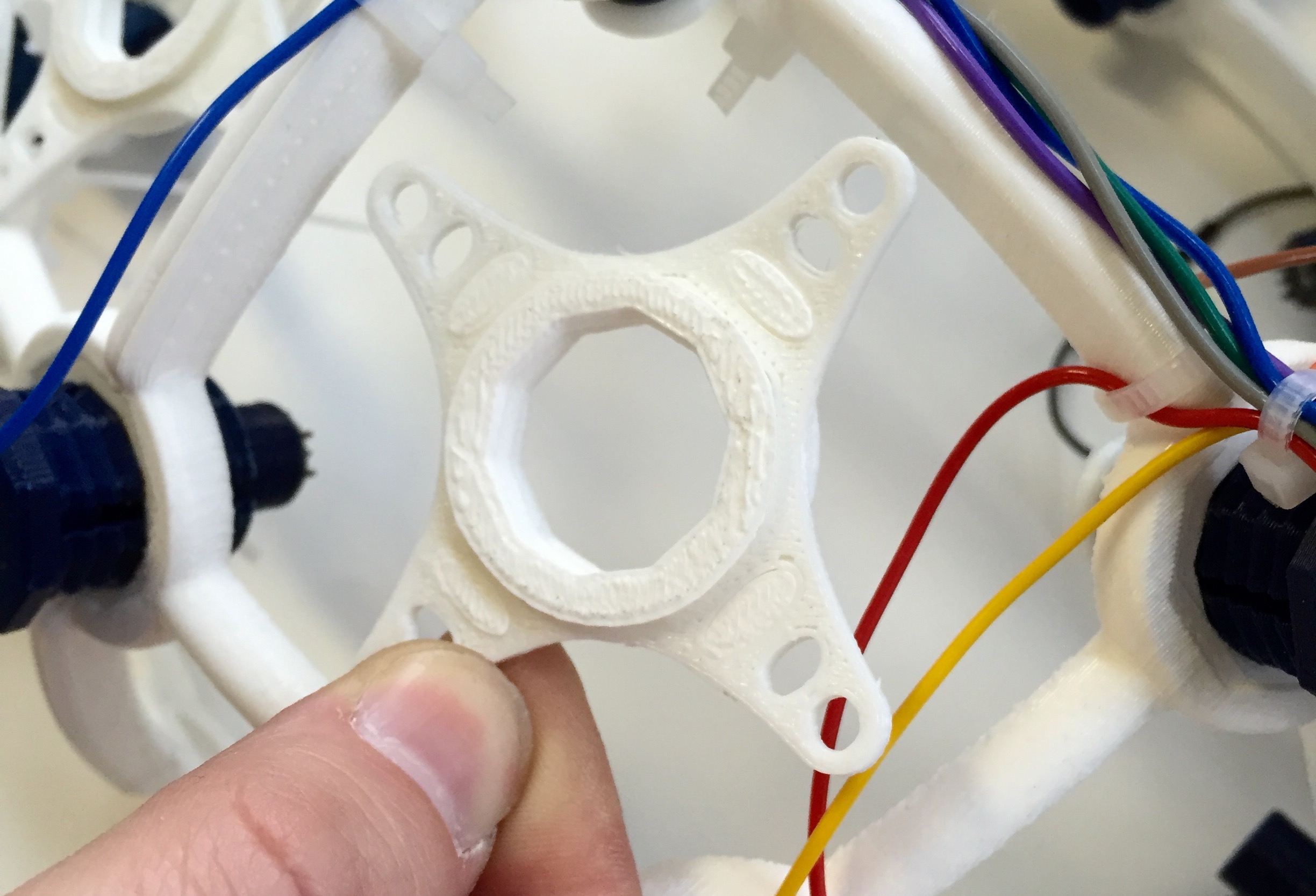
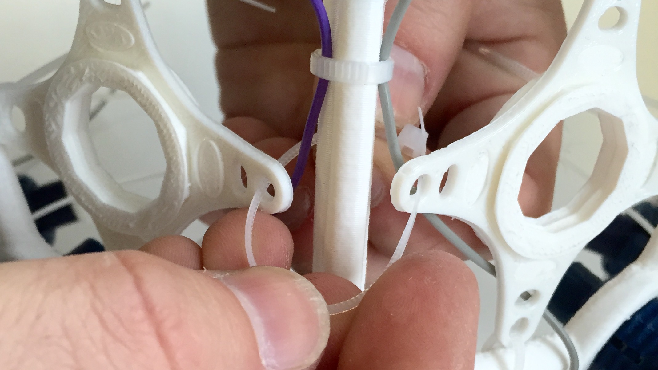
Zip Tie QUADSTAR onto frame
Using zip ties, tie down the corners of the QUADSTAR onto the frame of your ULTRACORTEX. You should be using four zip ties per QUADSTAR. For QUADSTARS that are next to each other, re-use the same zip tie to tie them both down to the frame. NOTE: Tie the QUADSTARS down loosely at first in order to ensure that they are all centered while tied down to the frame. Once all of the QUADSTARS are tied loosely to the frame, tighten them to secure them to the frame.
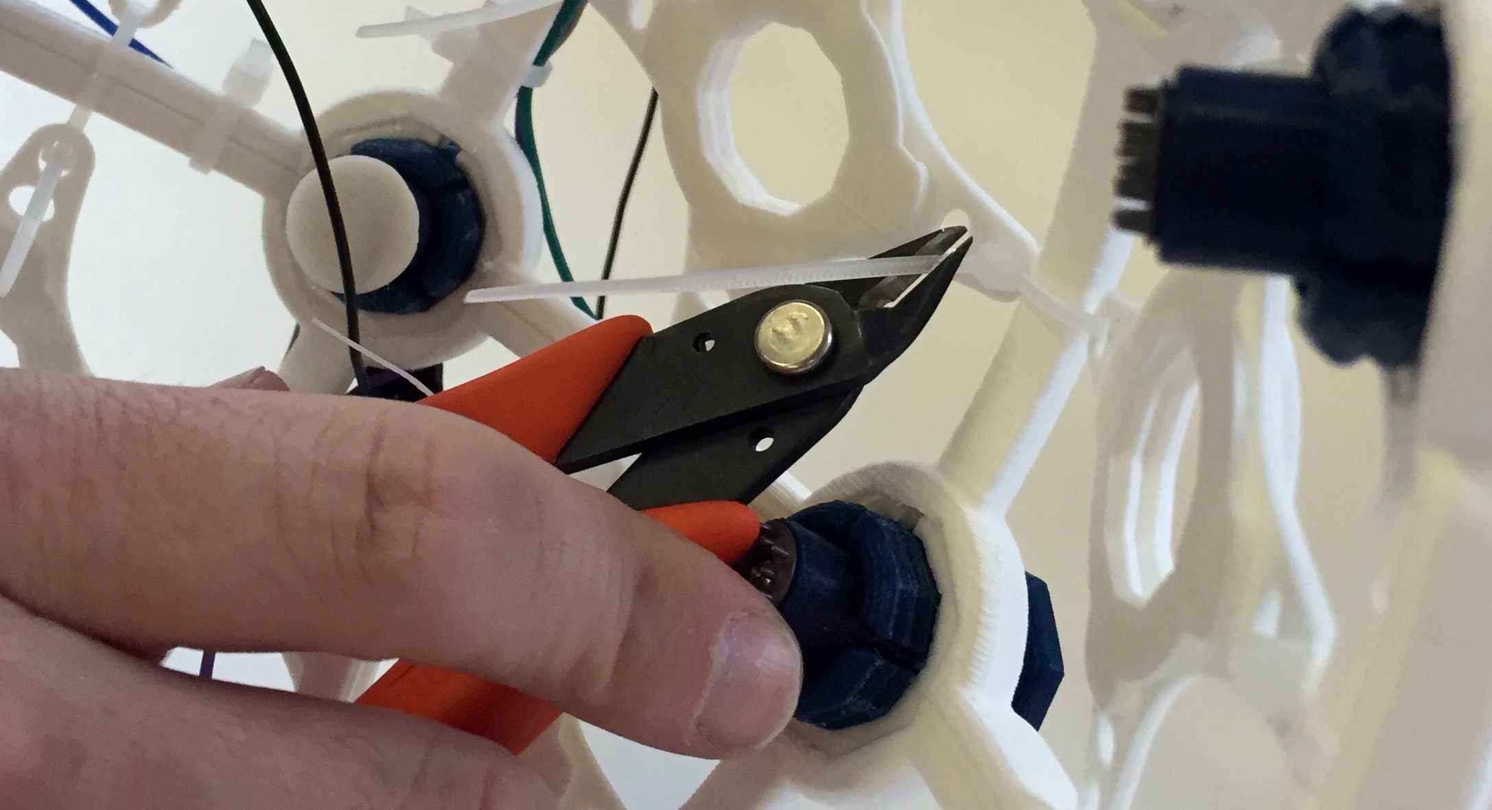
Cut Zip Ties
Turn the ULTRACORTEX over and snip off all of the loose ends of the zip ties.
Insert Comfort Nodes
Next, screw a comfort node into each of the 8 QUADSTARS.
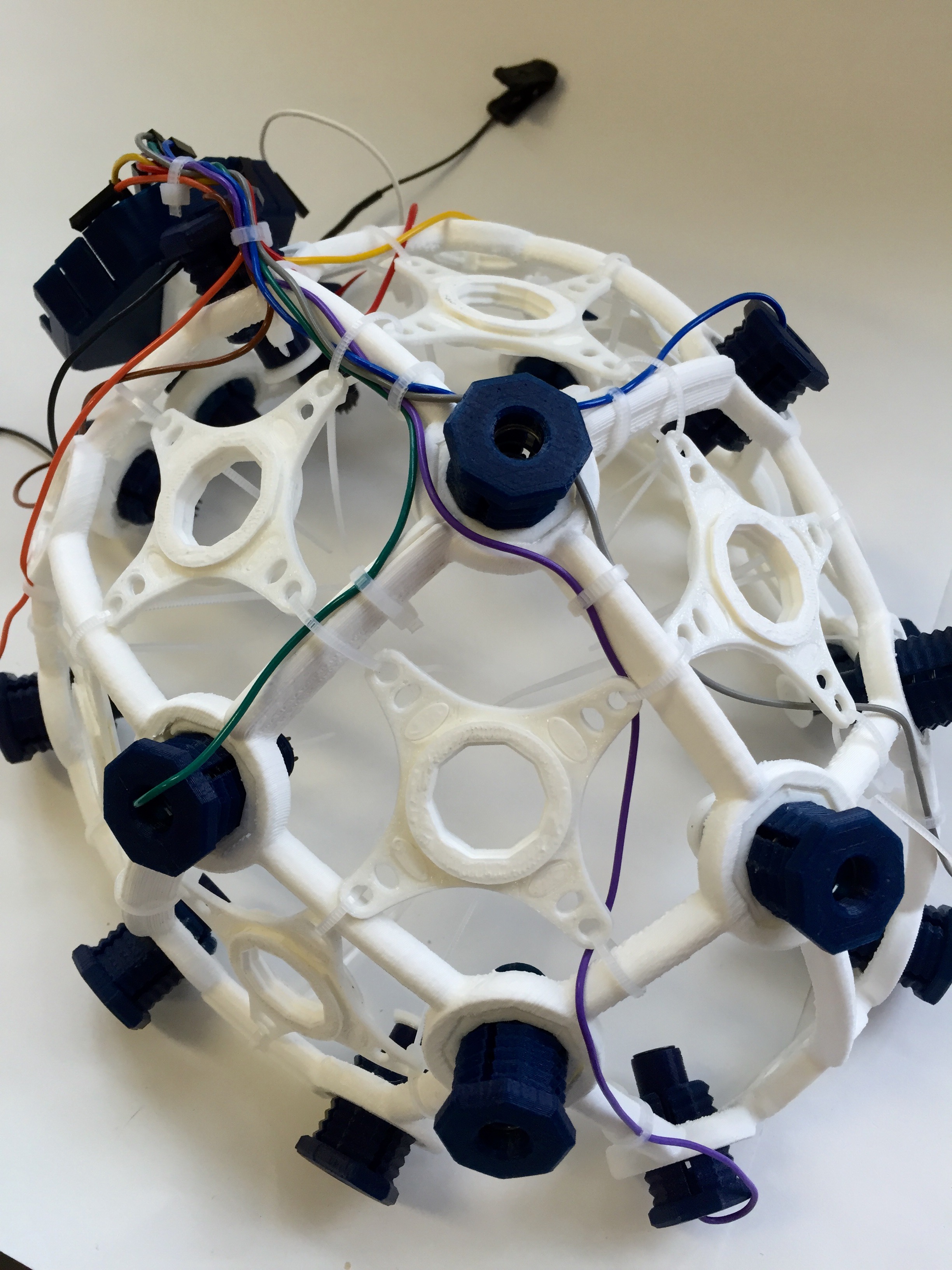
Supernova Assembly Complete!
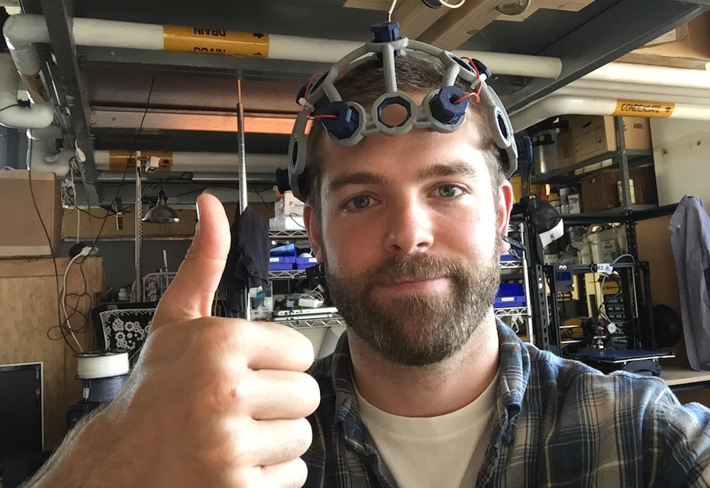
Adjust the Ultracortex for your head
Put the Ultracortex Mark 3 onto your head and gradually tighten the electrode units until the electrodes are snuggly (but comfortably) against your scalp. If it is difficult to twist the OCTABOLT pieces by hand, you may need to use the OCTATOOL as seen in the gif below.
Be careful not to strain the electrode wires when twisting the electrode unit with the OCTATOOL, or you may separate the wire from the electrode itself. Turn the OCTABOLT until the wire is nearly taught, then reposition the wire and tool and twist again, as demonstrated in the gif.
Examine your brain waves!
Place your UltraCortex on your head so that the back center node is roughly the same distance above your inion (bump on the back of your skull) as the front center node is above the bridge of your nose. As you place the UltraCortex on your head, the springs should adjust to the shape and size of your head.
Now that you have your Ultracortex assembled and comfortably adjusted to your head size and shape, it's brain wave time!
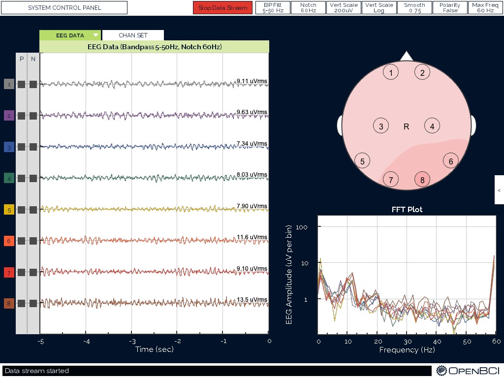
Check out the Getting Started w/ OpenBCI tutorial to get up-and-running with the OpenBCI Processing GUI.
Below is a screenshot of what the GUI looks like when you've got your OpenBCI + Ultracortex (w/ 8 channels) hooked up! You can see a nice alpha (~11 hz) spike on the FFT Plot.
Give Us Feedback!
If you have questions, comments, or suggestions regarding the printing and/or assembly of the Ultracortex, we'd love to hear from you. Please submit issues to this repository or email us at contact@openbci.com. Or take some pictures of yourself wearing the Ultracortex and Tweet at us (@OpenBCI & @Ultracortex)!