MyoWare OpenBCI Integration (Cyton Board)
THIS HARDWARE VERSION HAS BEEN DEPRECATED AND IS NO LONGER IN PRODUCTION.
MyoWare v1.0 is obsolete and has been pulled from production. The updated version is Myoware v2.0. This doc covers the integration of MyoWare v1.0 with the Cyton board.
You can purchase Myoware v2.0 from the OpenBCI Shop and connect to Cyton using the updated tutorial.
Overview
This tutorial will show you how to read EMG data (electrical signals from muscles) using a MyoWare board, an OpenBCI Cyton board, and the OpenBCI GUI. If you have a Ganglion board instead, check out our Ganglion board MyoWare integration tutorial!
Materials Needed
- MyoWare board
- OpenBCI Cyton board, with power source
- OpenBCI dongle
- Solid Gel Electrodes (for using the MyoWare board)
- Soldering iron and materials
- Two male-male jumper wires (like these), and three male-female jumper wires (like these)
Note: Jumper wires aren't sold on the OpenBCI website, but we used some from Adafruit (linked above) for this tutorial.
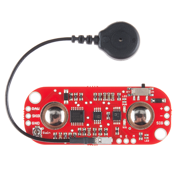
1. Soldering the MyoWare Headers
Solder 5 wires to the MyoWare board as shown below. Solder the male-male wires to the "+" and "-" connects, and the male-female wires to the R, E, and M connects.
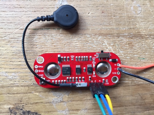
The wires attached to the "+" and "-" connects will be used to supply power to the board. They'll be attached to high voltage and ground outputs on the OpenBCI Cyton board.
The wires attached to the R, E, and M connects will transmit electrical signals from MyoWare's three electrodes to the OpenBCI Cyton board. R is the reference electrode, the one attached to the black wire. M is the middle electrode, and E is the end electrode. The E and M electrodes will measure activity across a muscle.
2. Preparing OpenBCI Cyton Board
Your Cyton board should look like this:
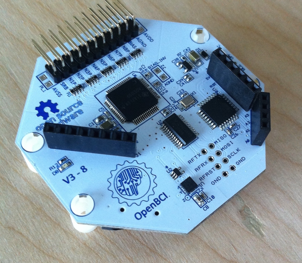
If your Cyton board is missing the black, female pin connectors (called "headers") sticking out of the board, you will need to solder them on before continuing.
3. Wiring the MyoWare Board to the OpenBCI Cyton Board
Connect the 5 wires from the MyoWare board in step 1 to the OpenBCI board, as shown below:
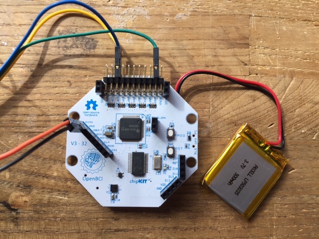
The "+" and "-" from the MyoWare board should go to DVDD and GND connects on the left side of the Cyton board. R, E, and M will connect to the pins at the top.
The wires should be connected like this:
| MyoWare Board | OpenBCI Board |
|---|---|
| + | DVDD |
| - | GND |
| R | BIAS (top pin) |
| E | N1P Top |
| M | N1P Bottom |
R, "+", and "-" must always go to the pins shown above. E and M can also be connected to N2P top and N2P bottom, or N3P top and N3P bottom, or any of the other two "NXP" pins.
When you have everything wired up, set the power switch on the MyoWare board to "on". Turn on the OpenBCI board, connect the USB dongle to your computer, and start the OpenBCI GUI software. If you're new to using an OpenBCI board with your computer, take a look at the Cyton Getting Started Guide.
4. Streaming EMG Data with the OpenBCI GUI
Attach three Solid Gel Electrodes to the three electrodes on the MyoWare board, and then stick the board on a muscle you'd like to monitor. The adafruit MyoWare tutorial has good guidelines for MyoWare board placement: (https:).
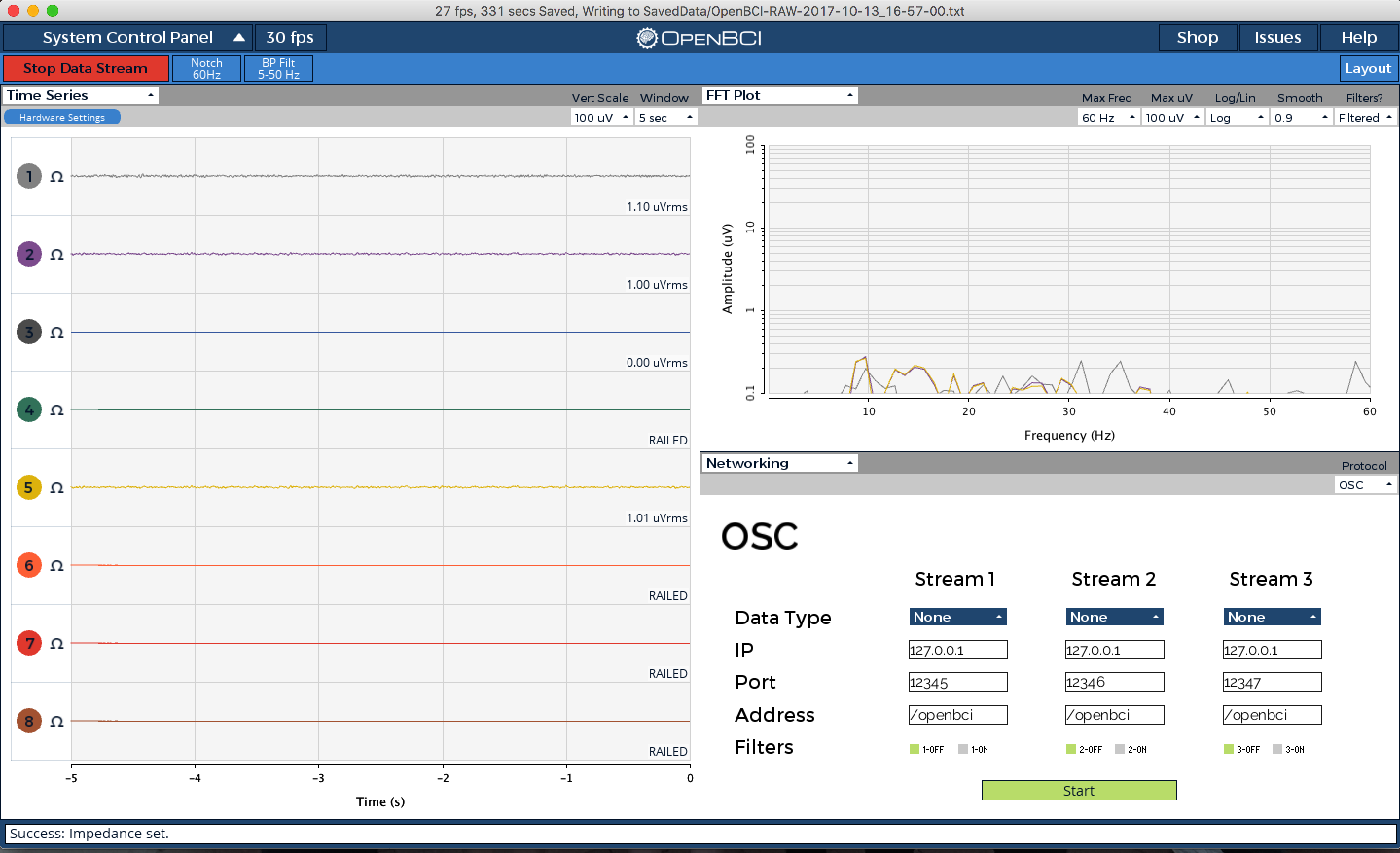
You'll be able to see signals from the MyoWare electrodes in the OpenBCI GUI. If you connected E and M to the N1P pins on the OpenBCI board, then the MyoWare data will appear in channel 1.
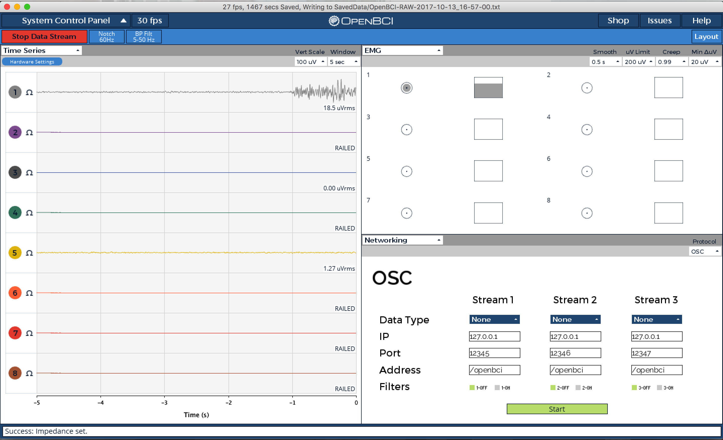
Here's what the GUI, and channel 1, will look like with the muscle at rest:
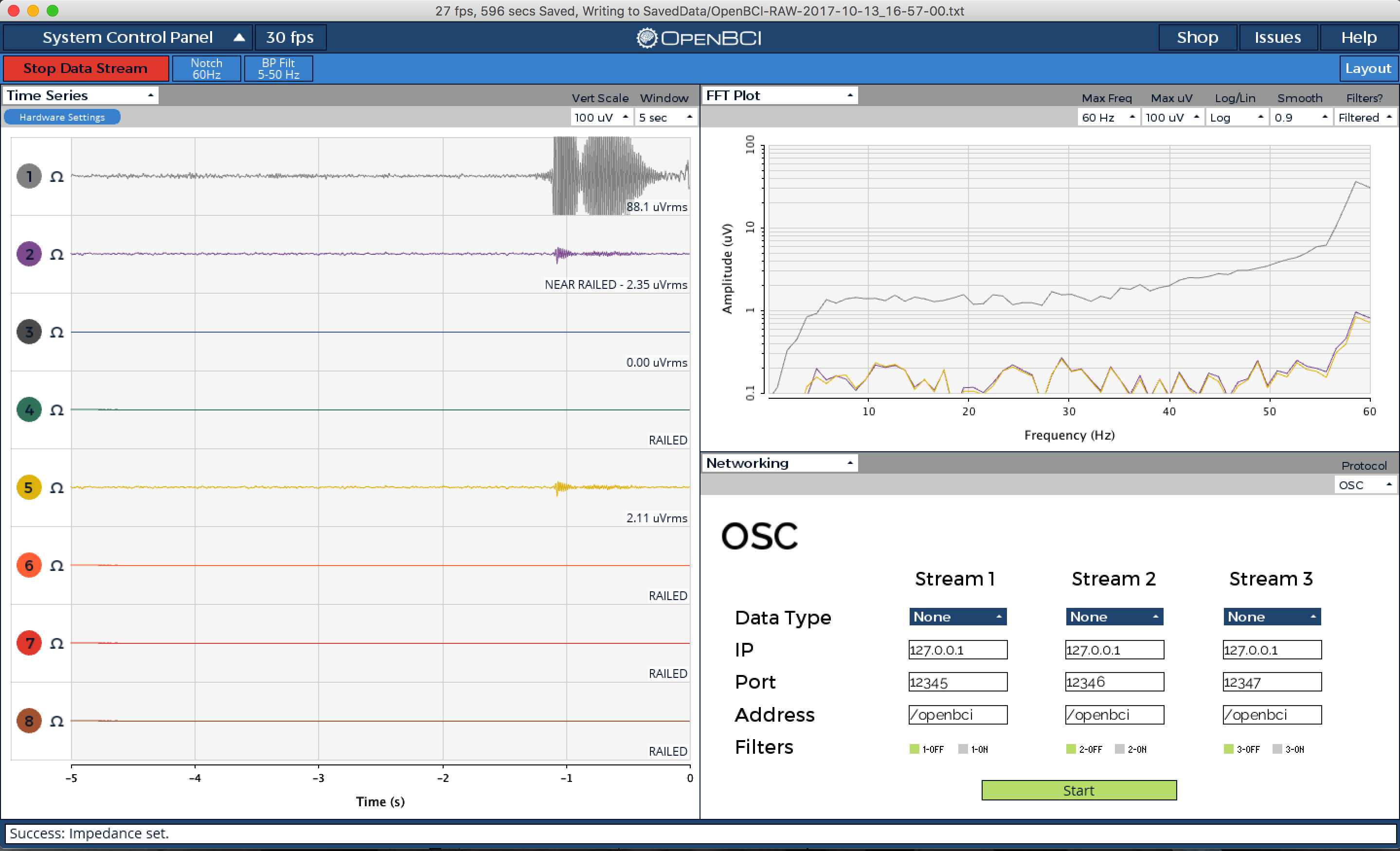
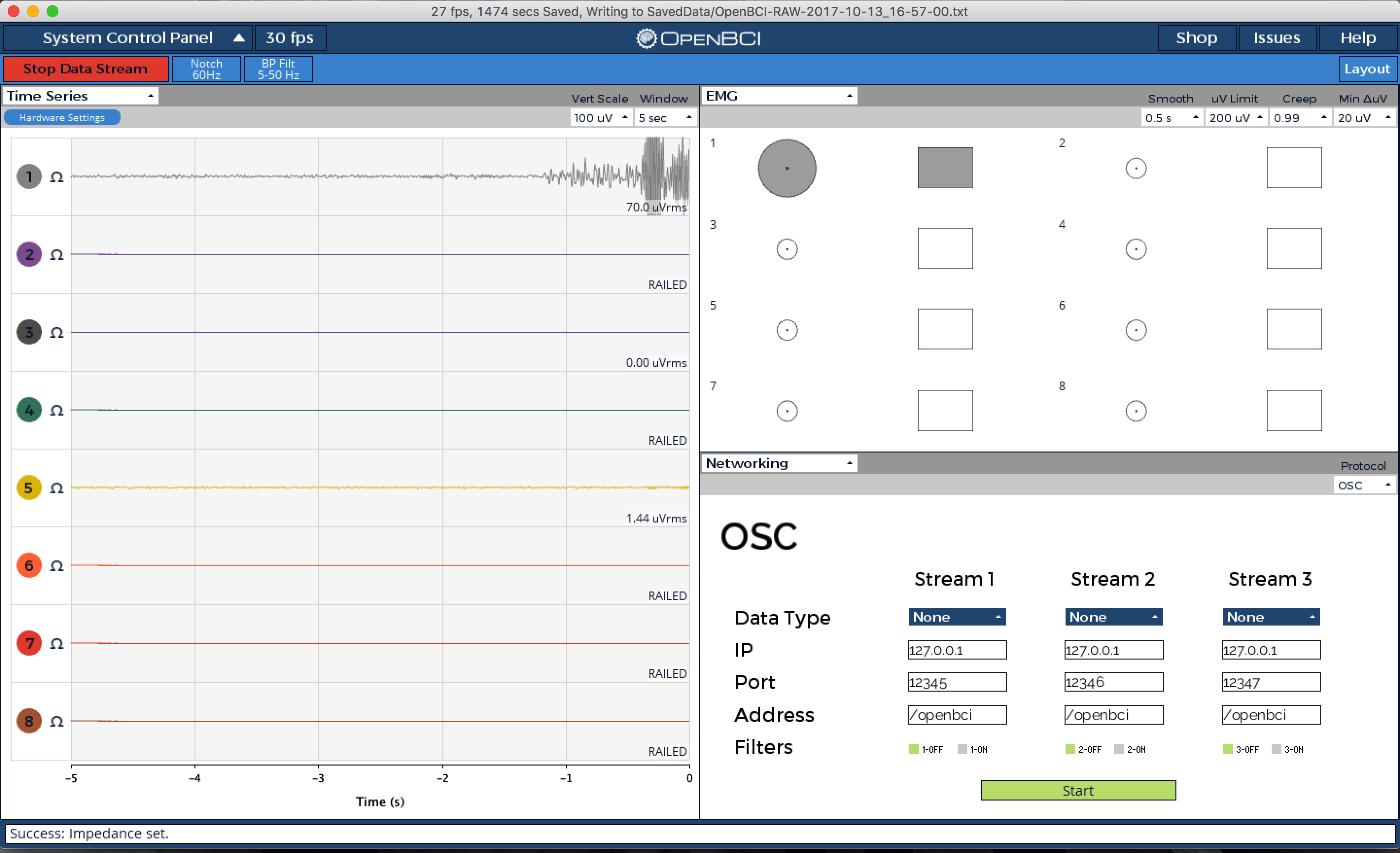
And here's what channel 1 will look like after flexing the muscle:
5. Using OpenBCI's EMG GUI Widget
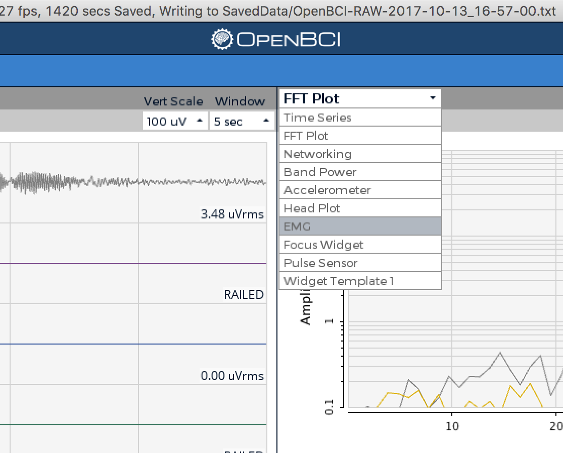
The OpenBCI GUI also has a widget for visualizing EMG data. To view it, click on the drop down menu under "FFT Plot", and select "EMG" instead:
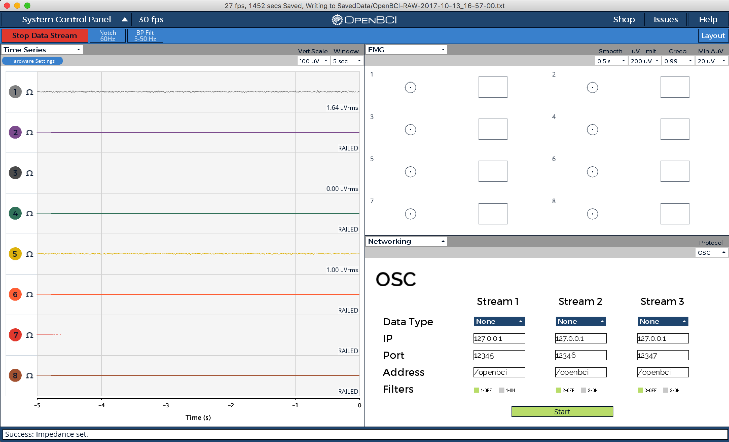
Each circle and box represents a channel. The circle and box fill up as the intensity of the signal on that channel increases.
Here's what happens to the GUI when a muscle is flexed a little (top) or very strongly (bottom):
You can use these changes in signal intensity to trigger analog or digital events from within the GUI as you like. Check out the W_EMG.pde file for more information on the EMG widget.