EMG-controlled LED
This tutorial is little more involved than the other EMG tutorials. No fear, we've documented every step below. Happy bio-hacking!
In this tutorial, we will show you how to change the color of an LED depending on your facial expression. To do that, we will read the peaks in EMG signals your face muscles produce when you flex them and use them to change the color of an LED. The yellow color will indicate smiling, the red color frowning, and the blue color a neutral expression.
Check out the example video of this tutorial being put into action!
The following instructions have been written for use with Windows 10.
Materials Required
- Computer or Laptop with OpenBCI GUI
- Cyton Board
- Arduino UNO or equivalent
- Gold Cup Electrodes
- Ten20 Conductive Paste
- USB Cable
- Blue, Red and Yellow LEDs - the number varies depending on the intensity
- 150 and 100 Ohm Resistors
- 3 NPN Transistors (one per color) such as the 2N2222
- Breadboard with Jumper Wires
Step 1: Hardware Assembly
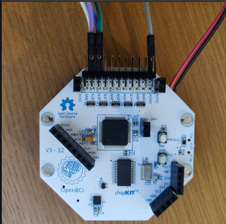
For this project you will need five gold cup electrodes. Connect the first electrode cable to the bottom AGND pin, and the other four electrode cables to the top and bottom pins of Channel 1 (N1P) and Channel 2 (N2P), as shown on the picture below.
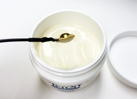
Now it’s time to connect the electrodes to your body. To connect a gold cup electrode to your skin, apply some Ten20 paste on it as shown in the picture below, and stick it to your skin. To secure the connection, you can put some medical tape over it.
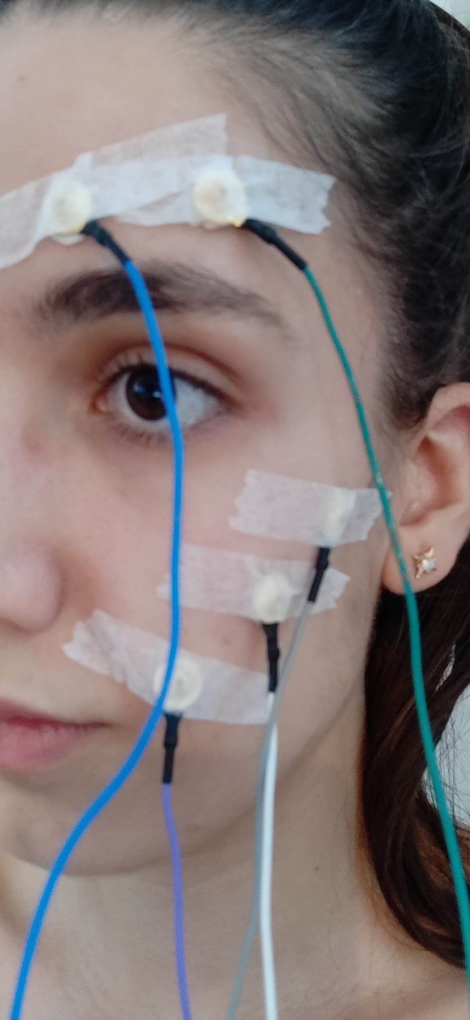
Now connect the five electrodes as shown on the picture below. The two electrodes on top of your eyebrow go to top and bottom N2P pins on the Cyton, the two electrodes closest to your mouth go to top and bottom N1P pins, and the electrode closest to your ear goes to bottom AGND. You can also use the color of the wires as a guide to know which electrode goes where.
| Electrode Wire Color | Cyton Board Pin | Body Location | Purpose |
|---|---|---|---|
| grey | bottom AGND pin | on face, close to ear | reference |
| purple | top N1P pin | corner of mouth | measuring potential difference on channel 1 |
| white | bottom N1P pin | middle of cheek | measuring potential difference on channel 1 |
| green | top N2P pin | outer brow | measuring potential difference on channel 2 |
| blue | bottom N2P pin | inner brow | measuring potential difference on channel 2 |
To assemble the circuit for the LEDs and Arduino, the first step is to connect the LEDs to the Arduino for each color. The connections are shown on the diagram below. For each color, yellow, red and blue, the Collector pin of the transistor (top connection in the diagram below) needs to be connected to 5 volts either through the USB pin or the 5V pin of the Arduino. Next, the Base of the transistor (middle pin in the diagram) gets connected to the Arduino GPIO pin of choice. In this case, we will use pin 12 for red, pin 11 for blue and pin 8 for yellow.
Finally, the LED gets connected to the Emitter pin of the transistor and to the Arduino pin GND through a resistor. In this way, the transistor acts as a switch to turn ON/OFF the group of LEDs while protecting the Arduino pin from receiving too much current.
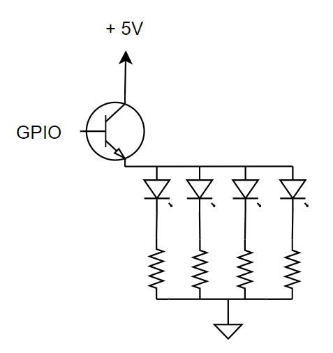
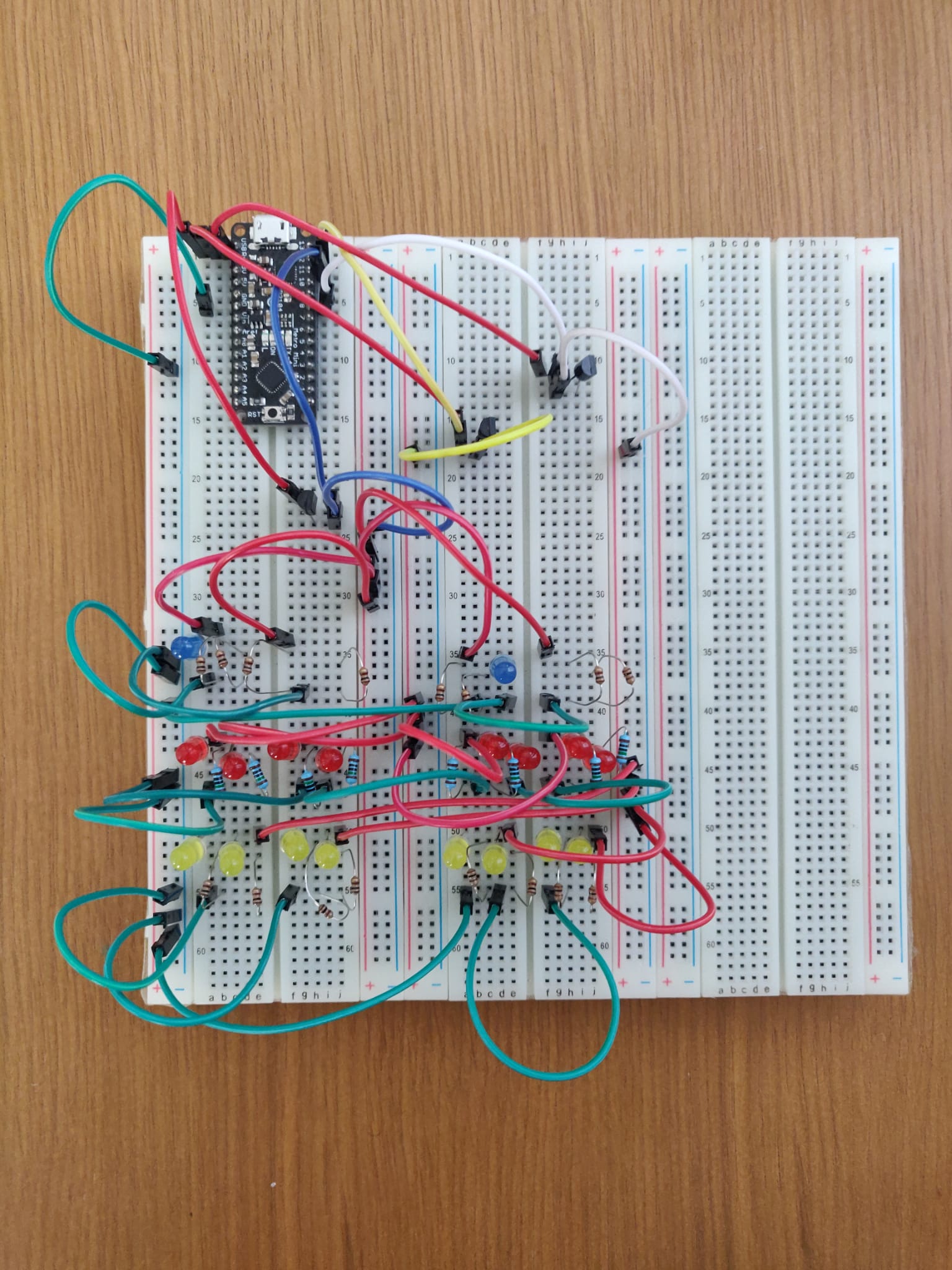
The diagram above needs to be replicated for every color, with as many LEDs as you like. An example breadboard set-up is shown below.
Step 2: Arduino Setup
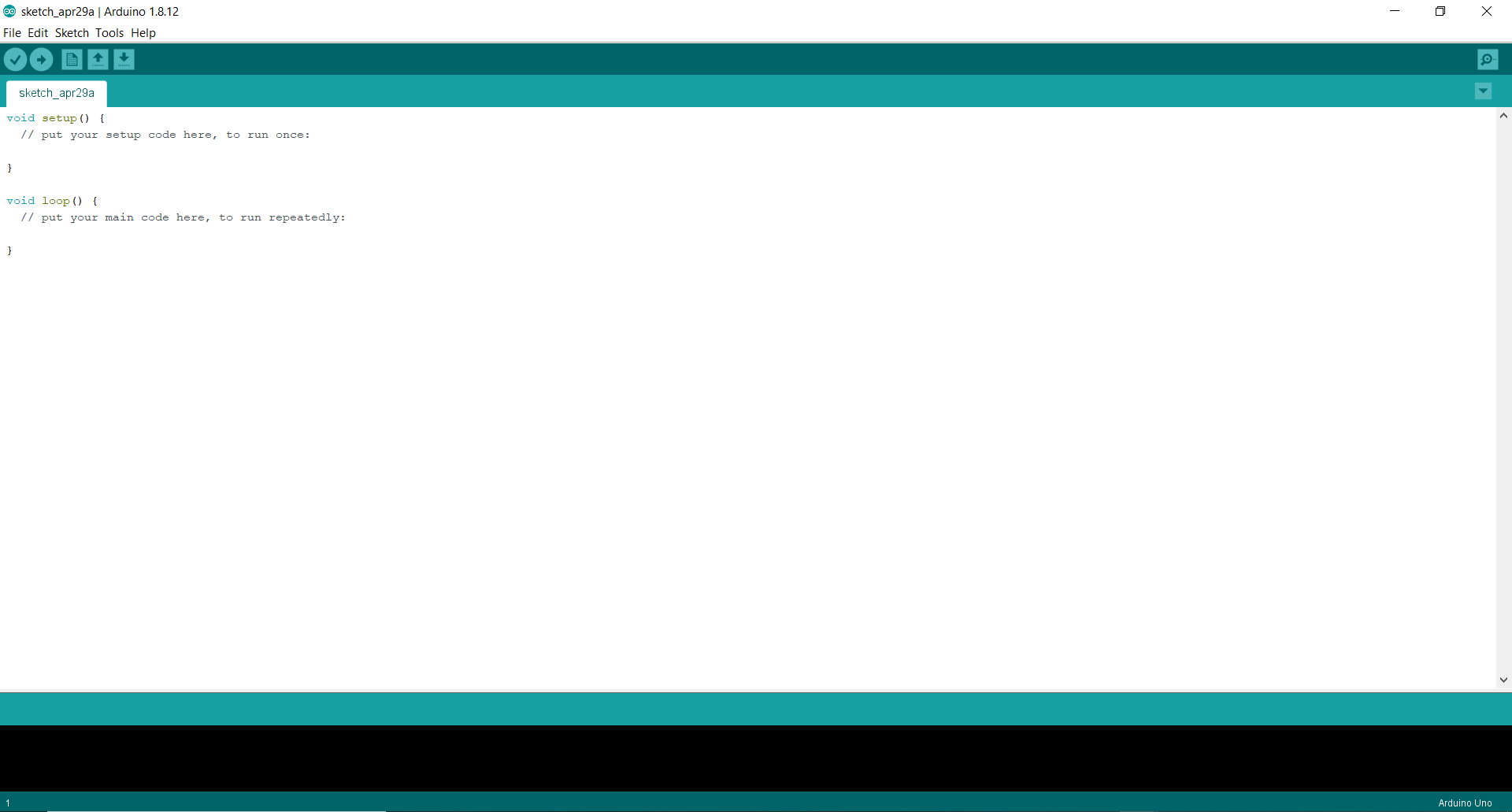
The first step is to download the Arduino IDE from here. Once you have downloaded and installed the Arduino IDE, you should see a screen like the one below.
Download the folder with the code from here and open it using the Arduino IDE by clicking on File >> Open... and selecting the entire folder. Connect the Arduino to the computer by clicking on Tools, then selecting the right Board and Port options. Next, click on Upload and wait for the code to be uploaded.
Once the code has been loaded into the Arduino, open the Serial Monitor in the Arduino IDE and try sending the commands ‘Y’, ‘G’, and ‘B’ to the Arduino. The LED color should change to Red, Green and Blue respectively if everything is correct. After testing, close the Serial Monitor.
Important: Don’t proceed to the next step until you have closed it.
Step 3: Software Setup
Download and install Python (either version 2 or 3). Python might already be installed on your computer. Type python --version to check if you have Python version 2 or 3 installed. To use this program, you need the following Python packages installed:
- pylsl: use
python -m pip install pylslfrom the Python folder in the command line to install it. - serial: use
python -m pip install serialto install it.
Step 4: Stream data using the GUI
Follow the Networking Tutorial to learn how to stream data using LSL from the GUI. For this project, you will need to stream the EMG data from Channels 1 and 2 using the Networking Widget. Your Networking settings should look as follows:
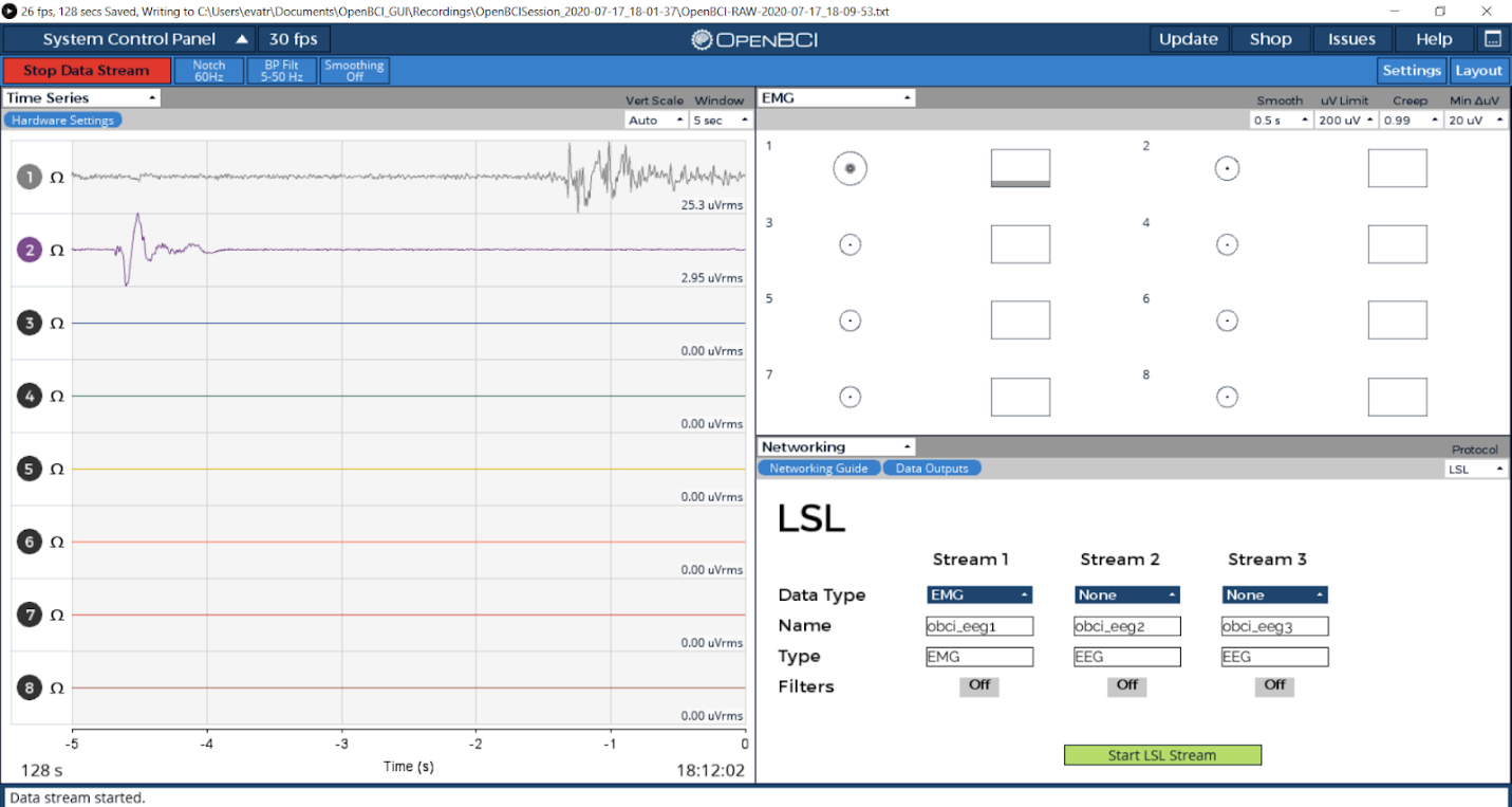
Important: Make sure your EMG widget is open before you start streaming.
Step 5: Using a Python Script to Send Data to the Arduino
The Python script will search for the EMG data streams. Once it finds them it will read it and detect any spikes that correspond to the face muscle flexing. If a flex is detected and 10 milliseconds have passed since the last flex, it will send the corresponding letter ‘R’, ‘Y’ or ‘B’ depending on which gesture was detected. The threshold for the time between flexes can be modified as needed to avoid debouncing.
Get the Python script from here by clicking on ‘Raw’ and copying it to a .py file in your Python folder. Once you’re streaming data from the GUI, go to the folder that you stored the script in from your command line, and run it using python.exe <script_name>.py
Hold the breadboard with LEDs towards your face in a dark environment and check how the color changes when you smile and frown. By modifying the time_thres and flex_thres parameters in the code, you can adjust the time to wait between flexes and the flex strength to your needs.
Try it out and send us a video of your final prototype!