External Trigger on OpenBCI Cyton Board
The Trigger Module Kit is an add-on to the OpenBCI Cyton and CytonDaisy Boards. It allows users to synchronize:
- Physiological Data: EEG or EMG
- Stimulus Timing: Event Markers/Trigger Signal
- Behavioral Data: Subject Response (button press)
EEG experiments require precise timing between external stimuli and the data stream. For example, P300 experiments require the stimulus timestamp in order to pinpoint the EEG signal that occurs about 300ms after the stimulus.
This tutorial explains how to add an external trigger to the OpenBCI data stream on the Cyton and Cyton+Daisy boards. Normally, the Cyton reads from the Accelerometer at 25 Hz. When the "Digital Read" or "Analog Read" widgets in the GUI are opened/enabled, signals are read from the GPIO pins at same rate as the NxP input headers. This allows for the precise timing required for external triggers.
Cyton External Trigger Kit Guide
Purchase the official kit from OpenBCI Shop
Contents
| Description | Use | Image |
|---|---|---|
| 3-pin Jumper Cables 25cm | Connect Sensors to Trigger Module | |
| 3-pin Jumper Cables 100cm | Connect Sensors to Trigger Module | |
| Photoresistor Module | Sensor to detect light stimulus | 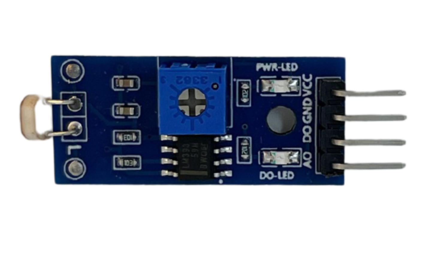 |
| Button Module | Sensor to register subject's response | 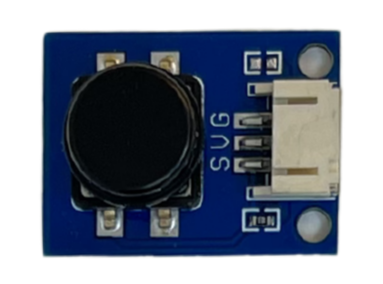 |
| Trigger Module | PCB that collects Sensor data | 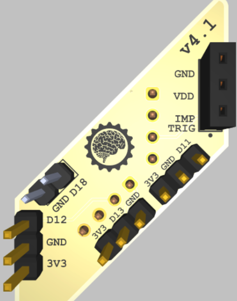 |
Assembly
You'll need the Trigger Kit + Cyton or CytonDaisy Board Kit.
- Plug lithium polymer battery into the back of OFF-power Cyton board
- Plug USB dongle into computer USB port
- Place Cyton Board into clear case, then seat Trigger Module as shown below
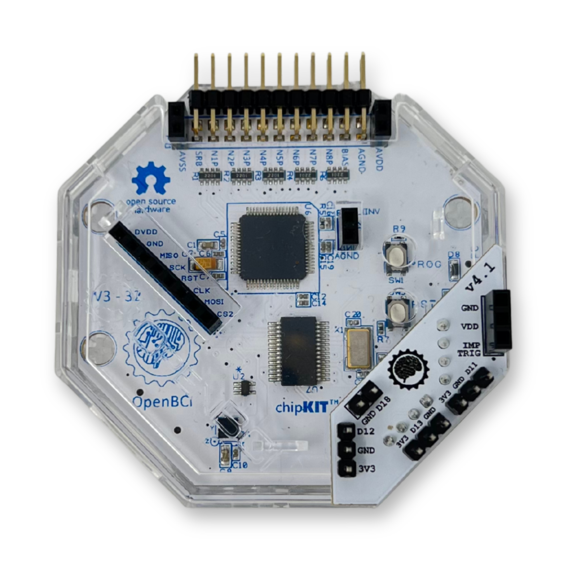
- Connect Button + Photoresistor to Trigger Module with Jumper Cables, as shown below. Make sure the pinout lines up with the trigger module. Reverse polarity will damage the system.

| Trigger Module Header Pin | Use |
|---|---|
| D12 | Photoresistor Module input |
| D13 | Button Module input |
| D18 | Input for external signals |
| D11 | Input for Myoware or Pulse Sensor |
| 3V3 | 3.3V source pin for external sensors |
| Up to 5 GND | One electrical ground per sensor |
NOTE: Do not use sensor signal with >3.3V amplitude. Signal amplitude higher than 3.3V will render the board permanently nonfunctional, and void the warranty.
- Flip Cyton Board power switch to 'PC'
Data
- Launch the OpenBCI GUI for your operating system following the tutorial for the OpenBCI GUI
- Open the Analog Read widget. The sensor(s) data appears here.

- Flash a light at the photoresistor module and confirm two LEDs light up, and data appears in Analog Read D12
- Press the button module and confirm the button press is logged in Analog Read D13
DIY Trigger Guide
Sections below are for those who can't or don't wish to purchase the Cyton External Trigger Kit and want to learn some Electrical Engineering through hands-on challenge.
Access the Digital Read Widget
Launch the OpenBCI GUI for your operating system following the tutorial for the OpenBCI GUI.
Once the GUI has launched, follow the guide to connect to the Cyton board from the OpenBCI GUI.
After connecting the board to the GUI, open and enable the "Digital Read" for one of your widgets.
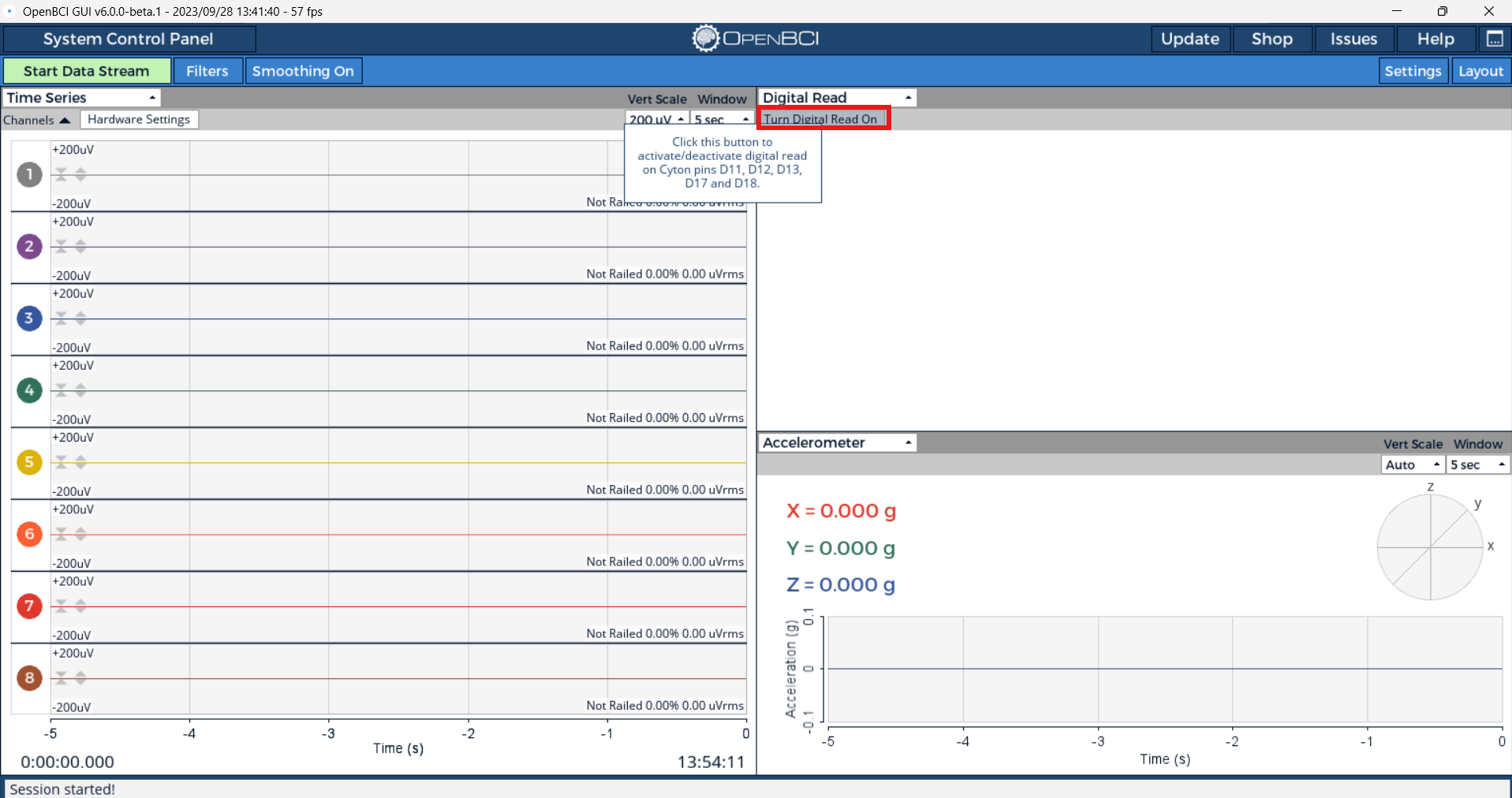
Then select the start digital read mode button in the top left of the newly populated widget. This will activate and send the proper commands to your Cyton. Note that the accelerometer will no longer be turned on because the trigger data is now sent instead.
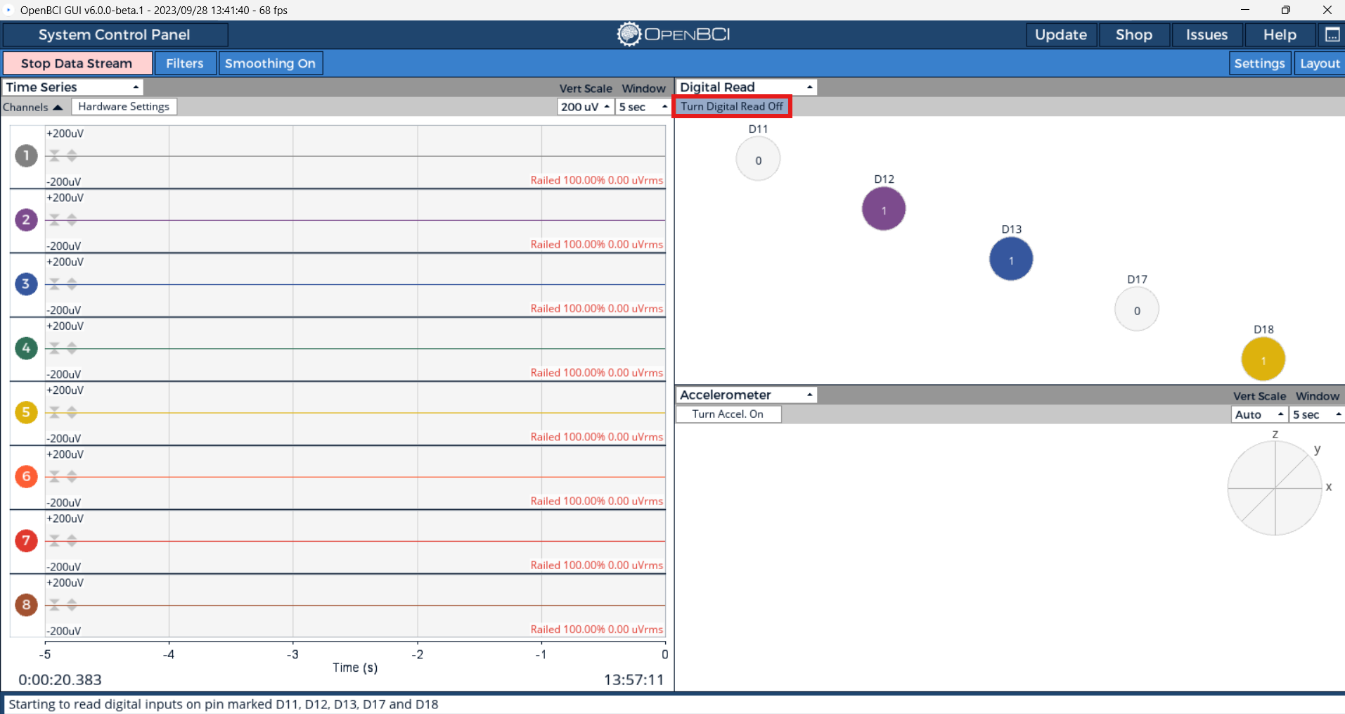
When you use a Cyton dongle, you get up to 5 GPIO (General Purpose Input and Output) pins to read from: D11, D12, D13, D17, and D18! If there appears to be a delay between when you press the button and when the digital read widget in the GUI shows the button pressed, then you may want to lower your serial port latency. Check out the guides for lowering serial port latency for Windows, macOS, and Linux!
Trigger Option 1: Cyton push button
The OpenBCI Cyton Board comes with a user-accessible pushbutton already on the board. This is the PROG button and it's attached to pin D17 with a 470K pulldown resistor. When you press the PROG button, D17 goes from LOW to HIGH. The PROG pushbutton is a great way to get user acknowledgment of a stimulus into the data stream.
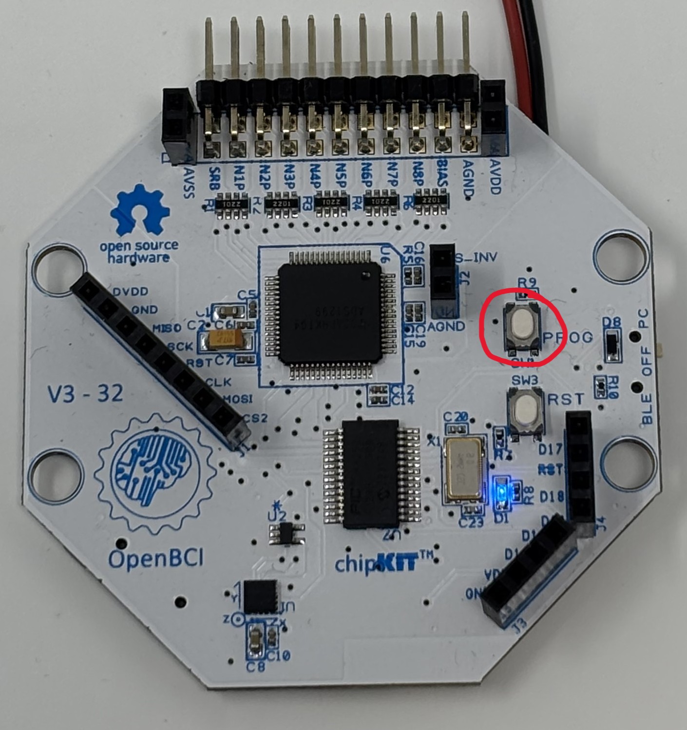
Shown below is an example of what happens when the PROG button is pressed.
The PROG button, when used along with the RST button, can put the board into programming mode, which will affect its normal operation. The blue LED will start blinking if it is in programming mode. To get the board out of programming mode and back to normal operation, refer to the "Did you Press the Reset Button?" guide.
We want to get the button press event into the data stream. (Reference the OpenBCI Data Format Doc for data packet format.) There are 6 bytes available in each data packet, and the default format is to read them as three 16-bit integers (aka 'words' or 'shorts'). You can decide to add your flags into the auxData array any way you choose. In this example, we are setting each short to the value 0x6620. That's because our OpenBCI GUI converts these variables to Gs (the GUI is expecting accelerometer data) and 0x6620 converts to PI (3.14). Our sample rate of 250SPS gives us a 4ms resolution on external trigger events like the rising edge of the PROG button press.
Here's an example of what the data looks like after it's been logged by our GUI:
217, -18.08, -23.04, -21.59, -29.86, -23.76, -19.65, -28.79, -19.47, 0.00, 0.00, 0.00
218, -18.17, -22.82, -21.59, -29.93, -23.85, -19.65, -28.72, -19.16, 0.00, 0.00, 0.00
219, -17.97, -23.04, -21.39, -29.97, -23.92, -19.56, -28.74, -19.24, 0.00, 0.00, 0.00
220, -17.99, -23.07, -21.61, -30.00, -23.72, -19.71, -28.52, -19.16, 0.00, 0.00, 0.00
221, -17.90, -23.04, -21.48, -30.09, -23.85, -19.54, -28.43, -19.18, 3.14, 3.14, 3.14
222, -17.90, -22.96, -21.48, -30.20, -23.72, -19.38, -28.57, -18.95, 0.00, 0.00, 0.00
223, -17.93, -22.89, -21.26, -29.97, -23.96, -19.65, -28.54, -18.95, 0.00, 0.00, 0.00
And here's an example of what the data looks like after it's been logged to the SD card:
D9,FFFCD7,FFFBF9,FFFC3A,FFFAC8,FFFBD9,FFFC91,FFFAF8,FFFC99
DA,FFFCD3,FFFC03,FFFC3A,FFFAC5,FFFBD5,FFFC91,FFFAFB,FFFCA7
DB,FFFCDC,FFFBF9,FFFC43,FFFAC3,FFFBD2,FFFC95,FFFAFA,FFFCA3
DC,FFFCDB,FFFBF8,FFFC39,FFFAC2,FFFBDB,FFFC8E,FFFB04,FFFCA7
DD,FFFCDF,FFFBF9,FFFC3F,FFFABE,FFFBD5,FFFC96,FFFB08,FFFCA6,6220,6220,6220
DE,FFFCDF,FFFBFD,FFFC3F,FFFAB9,FFFBDB,FFFC9D,FFFB02,FFFCB0
DF,FFFCDE,FFFC00,FFFC49,FFFAC3,FFFBD0,FFFC91,FFFB03,FFFCB0
Trigger Option 2: External Sources
Sometimes a situation may arise where you need to interface OpenBCI with an existing system, for example, an audio or visual event-related potential (ERP). In such a case, it is most desirable to have the onset of the signal tightly bound, temporally, with the EEG data. It is possible to interface the Cyton Board with the external signal-generating system using a few low-cost components. Our goal with OpenBCI is to make biosensing safe and fun. The most important thing is making sure that you can't accidentally plug yourself into the mains electrical supply. If you are interfacing an external trigger that is NOT operating under a battery supply, we recommend thinking twice about incorporating it into your system/protocol. If you have thought through it twice, here's how we do it when we need to.
Isolating the Cyton from an External Voltage
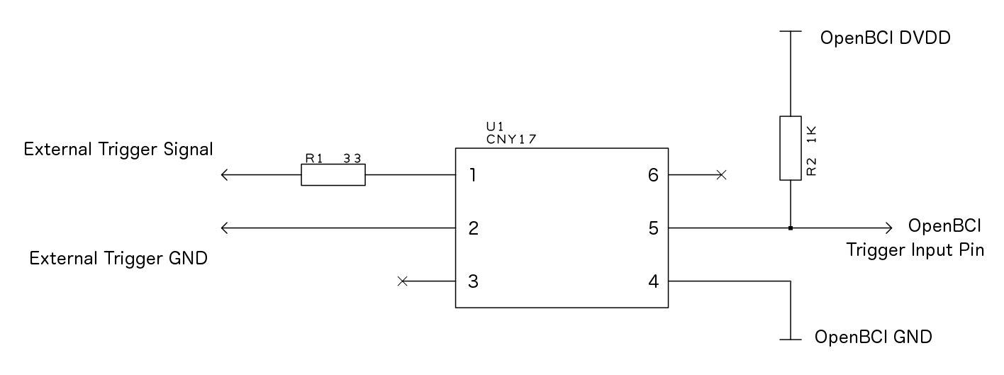
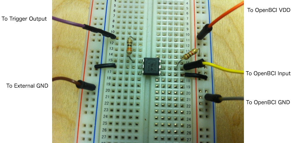
The simplest trick is to isolate the OpenBCI circuit from the trigger signal-generating circuit. For this purpose, we picked an optoisolator with 5000 volts isolation between the input and the output. The CNY17 family from Vishay is a great example of a low-cost, high-isolation optoisolator. It's usually available and costs under a dollar (USD) in singles. In the circuit to the right, when an external trigger of 3.3V is applied to the anode of the input (pin 1), the output (pin 5) will go from HIGH to LOW.
As always, help can be found at support@openbci.com and openbci.com/forum.