Ganglion Data Format
This discussion of the OpenBCI data format only applies to the OpenBCI Ganglion. The Ganglion contains a Simblee microcontroller that can both be programmed through the Arduino IDE or over-the-air (OTA). The Simblee has an on-board radio module. The format of the Ganglion data as seen on the PC is defined by a combination of the Arduino code on the Ganglion board and software on your computer.
Standard Bluetooth 4.n BLE Setup
OpenBCI Ganglion uses a standard Bluetooth 4.n (BLE) connection. Allowing connection to any BLE compatible device!
All BLE devices have specific Service, Receive, Send, and Disconnect, the ones for Simblee are:
| Service | Value |
|---|---|
| Service | fe84 |
| Receive | 2d30c082f39f4ce6923f3484ea480596 |
| Send | 2d30c083f39f4ce6923f3484ea480596 |
| Disconnect | 2d30c084f39f4ce6923f3484ea480596 |
Startup
Ganglion Board
The Ganglion does go through a reset cycle when its BLE connection is opened. Because of this, it's NOT possible to connect/disconnect from the Ganglion mid stream.
Initiating Binary Transfer
Once the Ganglion has initialized itself with a BLE connection it waits for commands. It sends no data until it is told to start sending data. To begin data transfer, transmit a single ASCII b. Once the b is received, continuous transfer of data in binary format will ensue. To turn off the fire hose, send an s.
Binary Format
Each packet contains a Byte ID followed by 19-bytes of data for a grand total of 20-bytes. The Byte ID determines how the receiving software or driver should parse the following 19-bytes of data. The Ganglion board samples biosignals at 200Hz, but the BLE radio is only capable of sending 20-byte packets at a rate of 100Hz. To overcome this limitation we only send the most significant bits of each Ganglion ExG (EEG, EMG, ECG) sample.
The Ganglion ExG data samples are 24-bit signed (2's complement), MSB first. If we did not compress the data, we could only fit one sample on each BLE packet because 24-bits is 3-bytes times 4 samples for each channel comes to 12-bytes, which would lead to a max sample rate of 100Hz (remember upper limit of consistent BLE transmission is somewhere around 100 packets per second). Therefore we aimed to get two samples per packet, which gives a real time 200Hz streaming sample rate.
The cost of this transmission strategy is a reduction in sample resolution, but this reduction is small. In the worst case scenario, only 18 bits of each 24-bit sample can be sent. This means that 6 bits of the sample are lost. This may seem problematic, but it's important to consider how the raw integer values sampled by the device convert into voltages. Each integer value corresponds to 0.001869917138805 uV (see the Interpreting the ExG Data section for more details). The lost 6 bits of information hold the least significant, or smallest, portion of the sample. In the worst case, the sample will be off by 2^6 = 64. Converting this to volts shows that, at worst, we lose 64 * 0.001869917138805 uV = 0.11967469688352 uV of resolution. In most applications, variations below 0.2 uV will be the result of environmental noise and no meaningful data will be lost.
Sample Transmission
We send ExG samples using either 19 bits or 18 bits. By default, 19-bit samples are sent. When the accelerometer or auxiliary features of the board are used, 18-bit samples are sent to provide room for the accelerometer or auxiliary data in the packet. Different packet ID ranges are used for 19-bit samples and 18-bit samples. This way, the controlling software that is running the decompression algorithm can decompress each packet without having to 'know' what state the system is in.
Both the 18-bit and 19-bit transmission strategies store the signed bit in the bit 0 or LSB position!
19-bit Sample Transmission
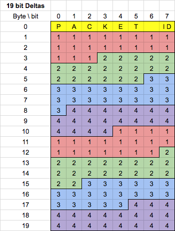
By default we use 19-bit sample transmission. In this strategy, the 19 MSBs of each sample are sent. Each packet sent with the 19-bit transmission strategy uses a Packet ID in the range of [100-199] (inclusive).
18bit Compression
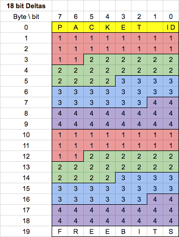
When the accelerometer or auxiliary features of the board are used, we use 18-bit sample transmission. Each packet sent with the 18-bit transmission strategy uses a Packet ID in the range of [0-99] (inclusive).
When the accelerometer is running, the default accelerometer sample rate is 10Hz. The Ganglion will acquire the accelerometer data whenever it is ready, but it will only send the values when packets with specific IDs are sent. For example, x-axis samples are sent every 1st, 11th, ..., and 91st sample. Similarly, y-axis samples are sent every 2nd, 12th, ..., and 92nd sample. See the below code for the full implementation.
void OpenBCI_Ganglion::sendCompressedPacket18() {
      radioBuffer[0] = ringBufferLevel;
      for (int i = 0; i < 18; i++) {
        radioBuffer[i+1] = compression_ring[ringBufferLevel][i];
      }
      if(useAccel){
        if(ringBufferLevel%10 == 1){ radioBuffer[19] = axisData[0]; }  // x axis
        if(ringBufferLevel%10 == 2){ radioBuffer[19] = axisData[1]; }  // y axis
        if(ringBufferLevel%10 == 3){ radioBuffer[19] = axisData[2]; }  // z axis
      } else if(useAux){
        if(ringBufferLevel%10 == 1){ radioBuffer[19] = auxData[0]; }
        if(ringBufferLevel%10 == 2){ radioBuffer[19] = auxData[1]; }
        if(ringBufferLevel%10 == 3){ radioBuffer[19] = auxData[2]; }
      }
      ringBufferLevel++;
      if (BLEconnected) {
        SimbleeBLE.send(radioBuffer, 20);
      }
    }
The Ganglion also has the capacity to send user defined auxData in the place of accelerometer data.
An n ASCII command is used to turn on the Ganglion accelerometer. Use an N to turn off the accelerometer.
Impedance Testing
The Ganglion has hardware in place that allows for testing the impedance of the electrode/skin contact. In order to do this, the controlling software uses the ASCII control bytes z to start impedance test and Z to stop impedance test. During impedance testing, the data stream is turned off. The Ganglion will send impedance values of all the channels, 1 to 4, and the REF input in series over and over until it receives a Z. The Packet ID values are listed in the chart below. The impedance data is sent as an ASCII string representing the measured value in ohms.
Verbose Prints
The Ganglion will sometimes send verbose data over the BLE connection. In this case, Ganglion can send from 1 to many packets of verbose ASCII data. The Packet ID for ASCII messaging will inform the computer if the message is not done and it should expect another packet 206 or 0xCE. When Ganglion is sending the last ASCII message packet, the Packet ID will be 207 or 0xCF.
Packet ID Cheat Sheet
| Byte ID Decimal | Byte ID HEX | Data Type | Description |
|---|---|---|---|
0 | 00 | 24bit | Raw uncompressed |
1-100 | 0x01-0x64 | 18bit | 18-bit compression with Accelerometer |
101-200 | 0x65-0xC8 | 19bit | 19-bit compression without Accelerometer |
201 | 0xC9 | impedance | Impedance Channel 1 |
202 | 0xCA | impedance | Impedance Channel 2 |
203 | 0xCB | impedance | Impedance Channel 3 |
204 | 0xCC | impedance | Impedance Channel 4 |
205 | 0xCD | impedance | Impedance Channel Reference |
206 | 0xCE | multi | Part of ASCII message |
207 | 0xCF | multiStop | End of ASCII message |
Interpreting the EEG Data
Once you receive and parse and decompress the data packets, it is important to know how to interpret the data so that the EEG values are useful in a quantitative way. The critical piece of information is the scale factor.
For the scale factor, this is the multiplier that you use to convert the ExG values from “counts” (the integer number that you parse from the binary stream) into scientific units like “volts”. Scale factor is set and baked into the hardware.
The physical voltage range of the MCP3912 ADC in the Ganglion is -15686uV to 15686uV. A signed 24-bit integer can hold a range of values from -8388608 to 8388607 (MSB holds the sign bit). That means that the scale factor is:
15686 uV / 8388607 = 0.001869917138805
Accelerometer data must also be scaled before it can be correctly interpreted. The equation used to scale Accelerometer data is as follows (We assume 4Gs, so 2mG per digit):
Accelerometer Scale Factor = 0.032