Cyton Radios Programming Tutorial
You do not need to do any board programming if you want to use the Cyton and Dongle out of the box. All OpenBCI boards ship already programmed, i.e., with firmware uploaded. Email support@openbci.com before attempting to update or alter board firmware, or if you think there is an issue with your board. DO NOT attempt to upload firmware to your Cyton board or dongle unless specifically instructed to do so.
If you're curious about how we do it, keep reading! If you want to start streaming EEG/EMG/ECG data right away, head over to Getting Started. Happy bio-sensing!
Overview
The OpenBCI Cyton boards come with a USB dongle that allows for communication between the board and your computer. There is an RFD22301 BLE radio module on the dongle and board that enables the communication. Here are some terms that are important to note:
- The radio module on the dongle is called the HOST
- The radio module on the Cyton board is called the DEVICE
- Host-Device pairs can be programmed to transmit on up to 25 discrete channels
This page covers how the radio link works and how to upload new firmware to the dongle radio and the board radio.
Setting up your system to program OpenBCI Radios
You will need:
- Computer (Windows or Mac or Other)
- Arduino IDE v1.8.19
- Custom RFduino libraries for OpenBCI
- A 0.1uF capacitor (see Device section below)
Steps:
-
Download and install the Arduino IDE v1.8.19.
-
Download the OpenBCI_RFduino repo from our GitHub.
-
Unzip the folder.
-
Now move the folder called RFduino and everything it contains to:
On a Mac
/Applications/Arduino.app/Contents/Resources/Java/hardware/arduinoOn a Windows
C:\Program Files (x86)\Arduino-1.5.8\hardware\arduinoOn Linux, put the RFduino folder and everything it contains in
arduino-1.5.8/hardware/arduino -
If you haven't already, then install the ChipKit Core as well
NOTE FOR LINUX USERS
Linux users will need to have the program wine installed in order to continue. There is a dependency for the Arduino code that requires running RFDLoader.exe.
To run this .exe, do the following:
- Navigate to the /hardware/arduino/RFduino folder
- Rename RFDLoader to RFDLoader.old (just in case)
- Replace RFDLoader with a script that uses wine to call RFDLoader.exe, forwarding the serial port.
- Drag RFDLoader to the RFduino folder
That's it! As long as wine is installed normally, the script should take care of any issues you may have when uploading.
Using Radio Firmware Version 2.x.x (Fall 2016)
Getting Radio Firmware Version 2.x.x (Fall 2016)
-
Download the OpenBCI_Radios Firmware repo from our github. You may also clone the repo into your libraries folder cited after step 6.
-
Unzip the folder, and if it is named OpenBCI_Radios-master, rename it to just OpenBCI_Radios.
-
Move the OpenBCI_Radios folder from your downloads into:
On Mac/Linux: Documents/Arduino/libraries
On Windows: C:\Users\username\Documents\Arduino\libraries
If there is no 'libraries' folder in the above folder, create one.
-
Open the Arduino IDE 1.5.8, restart the Arduino IDE if it was open.
If you want to modify the firmware that the OpenBCI Dongle came with, or roll your own, make sure that you are setting the RFduino up as a DEVICE, and that the channel is selected correctly.
Uploading Device Firmware to Cyton Board
Overview
In order to upload code to the Cyton Board RFduino, you need to have a serial connection to the computer. This is traditionally done with an FTDI cable breakout (SparkFun and Adafruit sell several). If you have an FTDI cable or breakout handy, make sure that it is a 3V device! Using a 5V FTDI device could damage the RFduino on-board OpenBCI! It is also possible to upload code to the board-mounted RFduino using the OpenBCI Dongle. This page will go over a few ways of uploading firmware to the OpenBCI Device radios.
Again, there is a small difference between the 8-bit and Cyton boards, explained below.
Upload DEVICE Radio Firmware Version 2.x.x (Fall 2016)
Steps:
-
In the Arduino IDE 1.5.8, go to
File-->Examples-->OpenBCI_Radios-->RadioDevice32bitto launch the Device firmware. -
Then go to
Tools-->Boardand selectRFduino. -
Follow one of the methods listed in the next section to connect the Device to your computer.
-
Now go to
Tools-->Portand select theCOMport (Windows) or/dev/tty.usbserial-*port (Mac/Linux) for your device or -
Click "Verify" on the toolbar (checkmark icon) to verify everything is ready. If you see
Done Compiling, then you are ready to go! -
Choose a channel number for your device. The channel number can be set in the code
radio.begin(OPENBCI_MODE_DEVICE,20);. -
Click "Upload" on the toolbar (the icon to the right of the checkmark). Your code is now uploading to the OpenBCI Device!
Important! As of firmware version 2, you must first flash the board with the line radio.flashNonVolatileMemory(); in the setup() function uncommented, then comment the line back out and program again. It is very important that you reprogram the board with the line commented out. We must do this because with firmware version two, the channel number is stored to non-volatile memory so we can change the channel number of the system from the PC/Driver, turn the system off, and still remember the newly set channel. If this is your first time uploading firmware version two (you bought your board prior to October 2016), you may ignore this message the first time you upload radio code.
Program DEVICE Radio with OpenBCI Dongle
The idea here is to use the FTDI chip on the Dongle to bridge USB to Serial for the upload process. There is a bit of preparation, and a special program for the Dongle radio so that it doesn't get in the way.
First, solder the headers that came with your OpenBCI Dongle. Then, move the switch to the RESET position, and upload some dummy code to the Dongle radio so that it doesn't interfere with the serial upload process.
Upload Pass Thru Radio Firmware Version 2.x.x (Fall 2016)
Go to the Arduino IDE 1.5.8 and do File-->Examples-->OpenBCI_Radios-->RadioPassThru32bit. Make sure to select RFduino from Tools-->Board-->RFDuino.
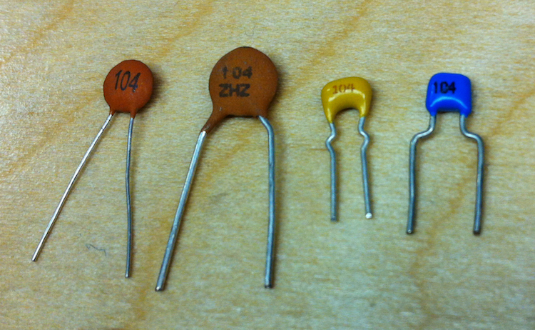
Next, you need a breadboard, 8 jumpers, and a 0.1uF capacitor. 0.1uF capacitors are small and lentil-shaped, and have the number 104 printed on one side. You can order them online from Amazon, eBay, or a hobby electronics store. If you have blue buttons on your board, you do not need the 0.1uF capacitor because it is already on the board. The 0.1uF capacitor needs to be in series between the Dongle GPIO6 pin and the OpenBCI Board RESET pin.
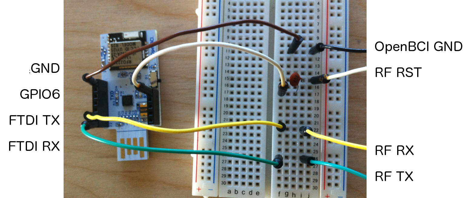
Here's a picture of the connections that you need to make. Power the OpenBCI board with the battery pack it came with, so you only need these four connections to do the upload. You could also power the OpenBCI board with 3V from the Dongle, but that makes the next step a bit trickier. In any case, these are the basic pin connections that you need to make when powering the board with a battery pack:
- FTDI RX --> RF TX
- FTDI TX --> RF RX
- GPIO6 --> 0.1uF Cap --> RF RST
- GND --> GND
On the 8-bit Board, the pins you need to connect to are accessed from the TOP of the board. Insert the jumpers into the holes in the correct position, and press them tightly against the sides of the holes to make a strong connection. Now, you can upload Device code to the RFduino on the OpenBCI 8-bit Board!
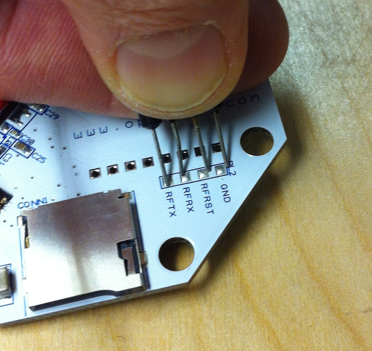
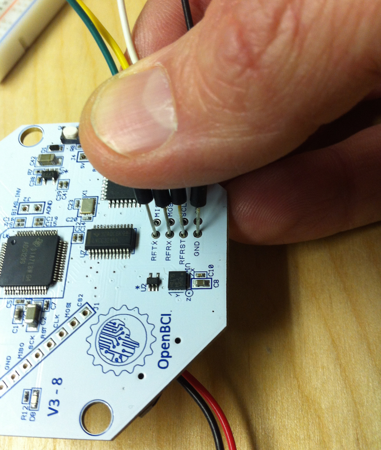
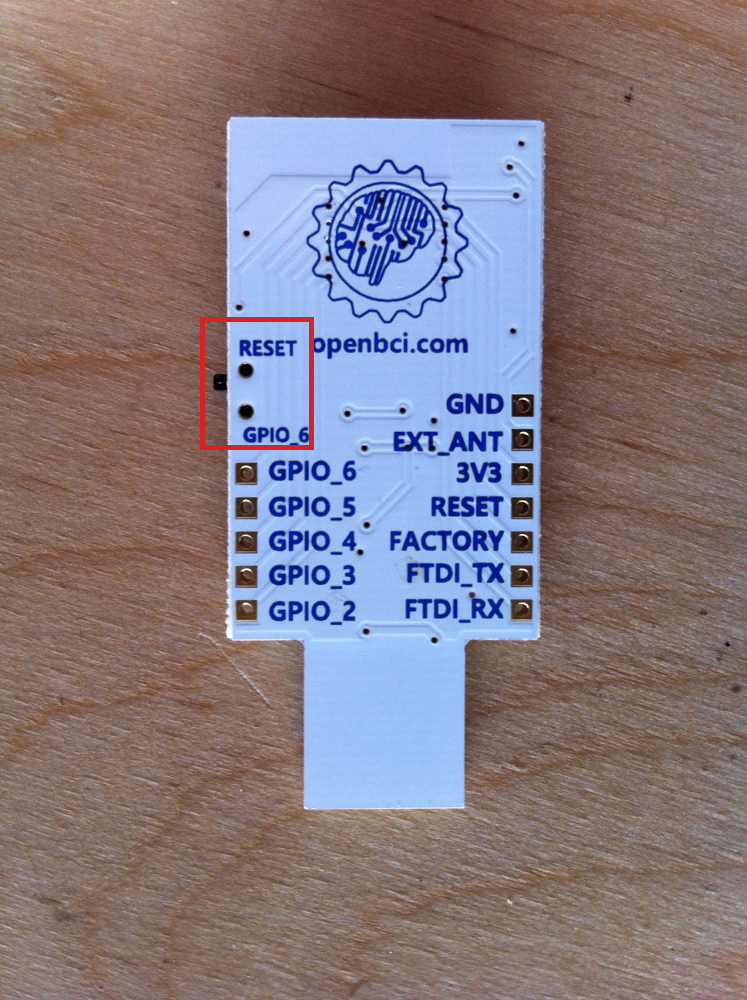
On the Cyton Board, the pins you need to connect to are accessed from the BOTTOM of the board. Connect the jumper wires to the center of the pads as shown and press tightly while uploading to the Device. Helpful tips:
- Use a 4pin female header to keep the wires in place
- Don't move your hand at all
- Place the board on a table or hard surface
- Keep the pins straight up and centered on the pads. (perpendicular to the surface of the pads)
There is a trick to it; it may take you a couple of tries to get good at it. On Mac, it does not matter if you select /dev/cu.* or /dev/tty.* in the port selection on the Arduino IDE.
Program Device Radio with Other FTDI Boards
There are many FTDI chip breakouts and cables out there that you can use. Here are a couple of examples of popular devices.
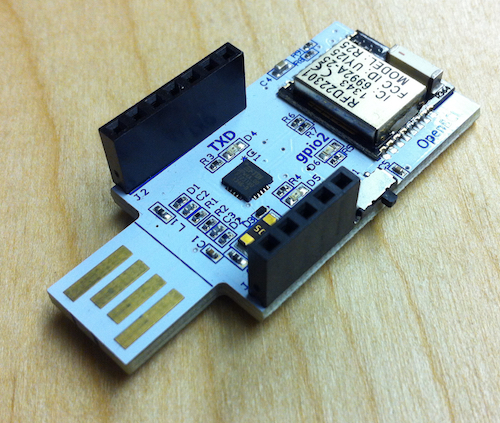
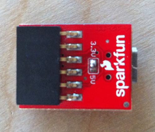
RFduino
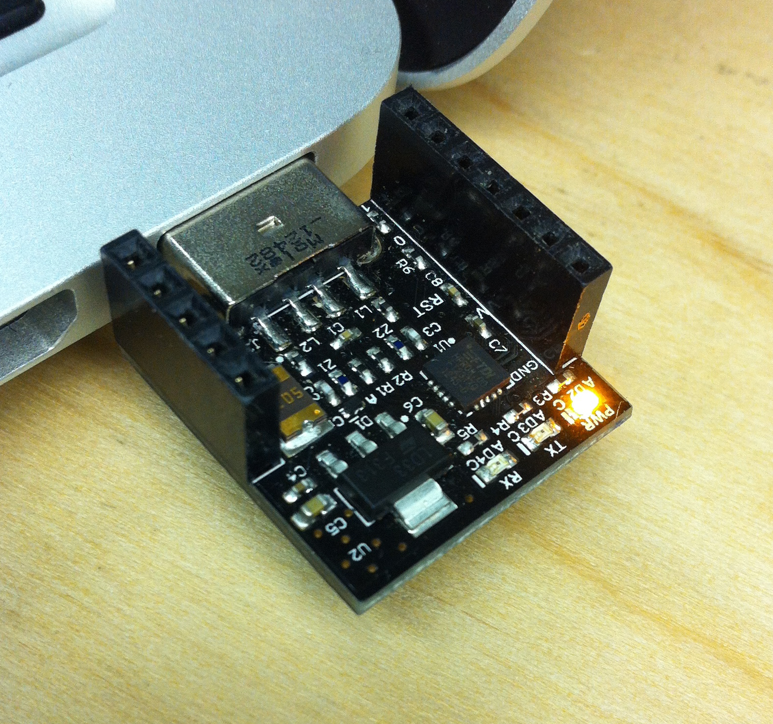
RFduino makes a small board that they call a USB Shield. The form factor and pinout of the OpenBCI Dongle matches exactly the pinout of the RFduino USB Shield. It's almost like we planned it that way ;) The only thing to change is that the GPIO6 is not the same as the OpenBCI Dongle. Connect the OpenBCI pin RF RST to the RFduino USB Shield pin RESET. And, you don't need to provide a 0.1uF cap, because the USB Shield comes with the 0.1uF capacitor already installed!
FTDI Friend
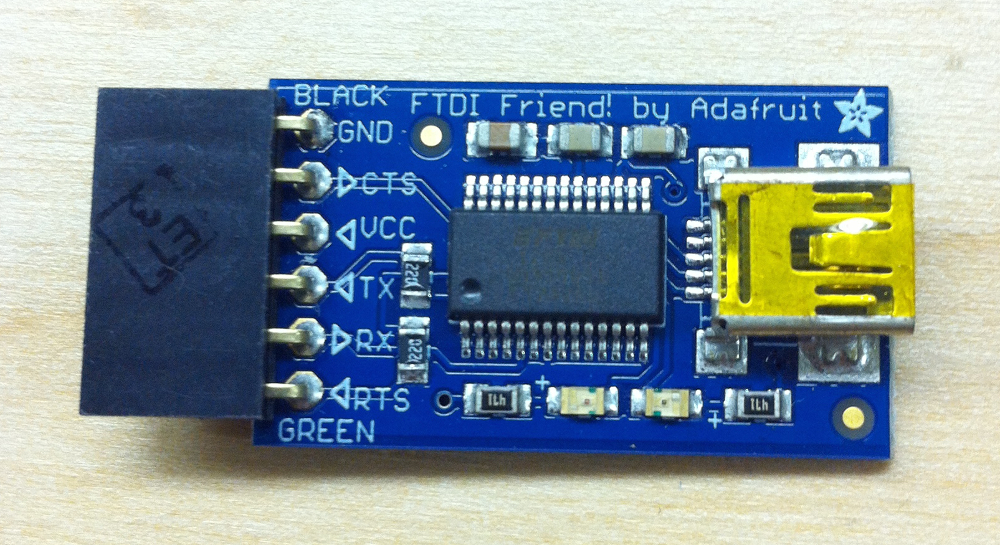
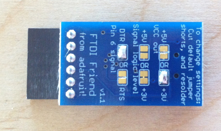
Another example would be the FTDI Friend from Adafruit. In this case, the pin labeled 'RTS' is the one you want to connect to the RF RST on the OpenBCI board. We need to ensure that the 'RTS' pin is behaving correctly and that we're sending 3V logic out! Note the image of the back of the FTDI Friend. I have jumped the pads marked DTR, and also the 3V pads on VCC out. The Signal Logic Level already has the 3V pads jumped. I cut the trace on the RTS and 5V pads as well. These are the correct settings for uploading to RFduino using FTDI Friend. The 'RTS' pin jump to OpenBCI RF RST connection will also need a 0.1uF series capacitor. These breakouts are awesome, but they can be a little advanced.
FTDI Basic Breakout
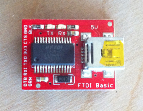
Sparkfun makes an FTDI breakout as well, and they come in a couple of flavors: 5V and 3V. By now, you know that you want the 3V Version. [pic coming soon] The Basic Breakout isn't as fancy as the FTDI Friend, but you do need to put a 0.1uF capacitor between the DTR pin and the RF RST pin. Also, if you have a version of this board with a voltage selection on the back, make sure that it has the 3.3V pads connected and the 5V pads cut!
Uploading Host Firmware to the OpenBCI Dongle
Overview
This process does not require third-party hardware. Before you begin, note that there is a switch on the dongle that allows for selection between RESET and GPIO6. This switch routes the DTR pin from the FTDI chip to either RESET or GPIO6 pin on the RFduino module. When the switch is in the GPIO6 position, the Dongle is ready for general communication, code upload, and streaming data mode to the OpenBCI Board. When the switch is in the RESET position, it is possible to upload code to the RFduino right there on the Dongle.
Upload HOST Firmware Version 2.x.x (Fall 2016)
Steps:
-
In the Arduino IDE 1.5.8 go
File-->Examples-->OpenBCI_Radios-->RadioHost32bitwhich will launch the Host firmware. -
Then go to
Tools-->Boardand selectRFduino. -
Plug the Dongle into your computer. Flip the switch to the
Resetposition if it is not already. -
Now go
Tools-->Portand select theCOMport (Windows) or/dev/tty.usbserial-*port (Mac/Linux) for your device or -
Click "Verify" on the toolbar (checkmark icon) to verify everything is ready. If you see
Done Compilingthen you are ready to go! -
Choose a channel number for your device. The channel number can be set in the code; see
radio.begin(OPENBCI_MODE_HOST,20);. -
Click "Upload" on the toolbar (the icon to the right of the checkmark). Your code is now uploading to the OpenBCI Dongle!
Important! As of firmware v2.X.X, you must first flash the board with the line radio.flashNonVolatileMemory(); in the setup() function uncommented, then comment the line back out and program again. It is very important that you reprogram the board with the line commented out. We must do this because the channel number is stored to non-volatile memory so we can change the channel number of the system from the PC/Driver, turn the system off, and still remember the newly set channel.