OpenBCI WiFi
::: info This product is no longer offered for sale due to reliability issues. Documentation is kept here for devices in-the-wild that are still in use. :::
The OpenBCI Wifi Shield was designed in partnership with Push The World. The OpenBCI Wifi PCB was designed with KiCAD, an Open Source PCB capture software. You can find a link to download KiCAD in our OpenBCI design files repository where you will find design files and component library files to load into KiCAD and edit, if you like, along with the full BOM for this maiden production run.
About the WiFi Shield
IMPORTANT NOTE: This product is in beta mode. The WiFi shield is known to have reliability issues across different computer configurations. Using it effectively requires advanced technical skills and programming knowledge. Please proceed at your own risk. OpenBCI cannot guarantee that the device will work with your configuration.
Wifi Board Specs
- Power with 3.3V to 6V DC battery ONLY
- Current Draw: 150mA connected and streaming data
- ESP8266 Wifi module (Arduino Compatible)
- Board Dimensions 2.41" x 2.41" (octagon has 1" edges)
- JST Power input
- Switch to stop power to external board
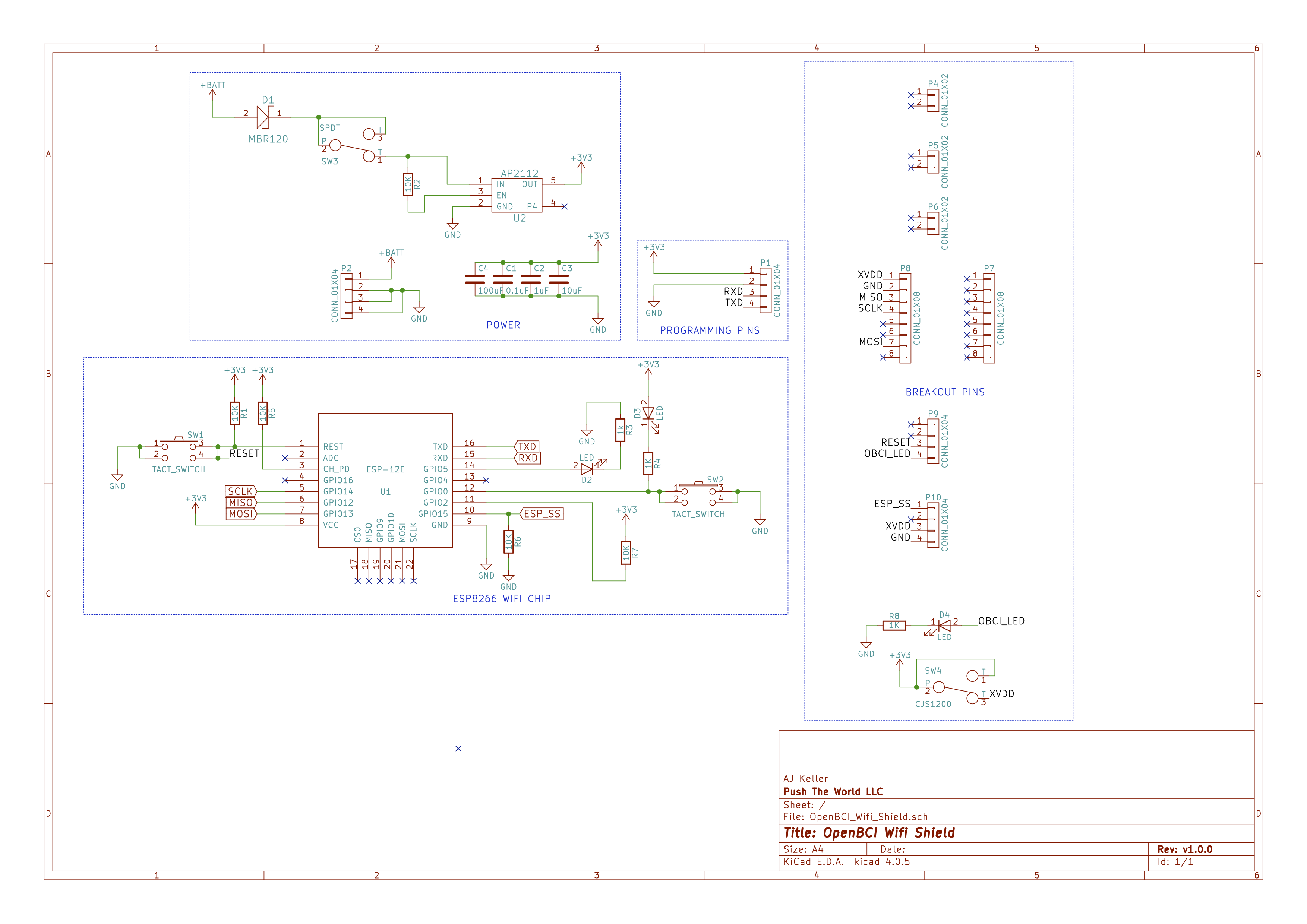
Wifi Board Circuit Schematic
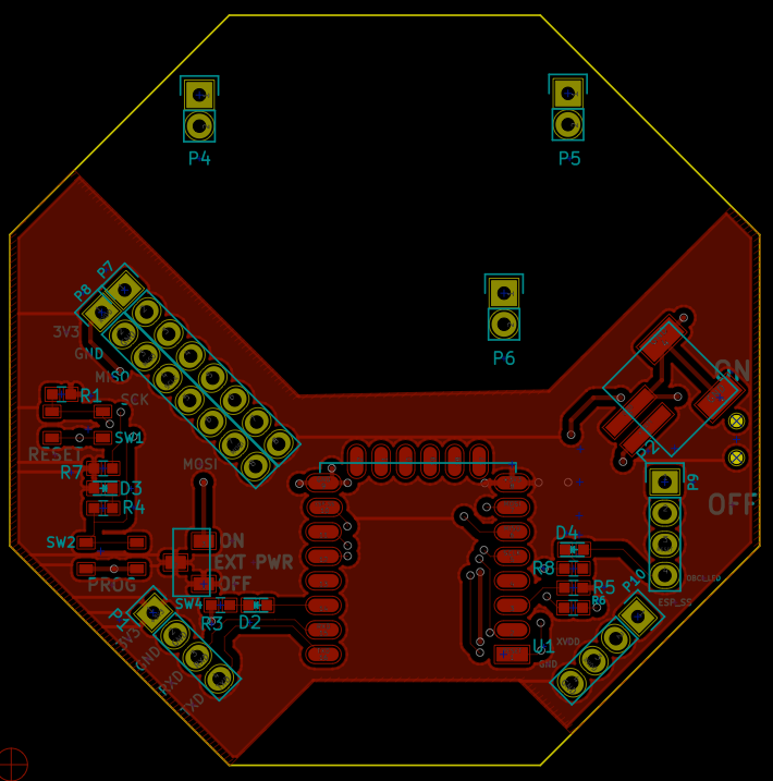
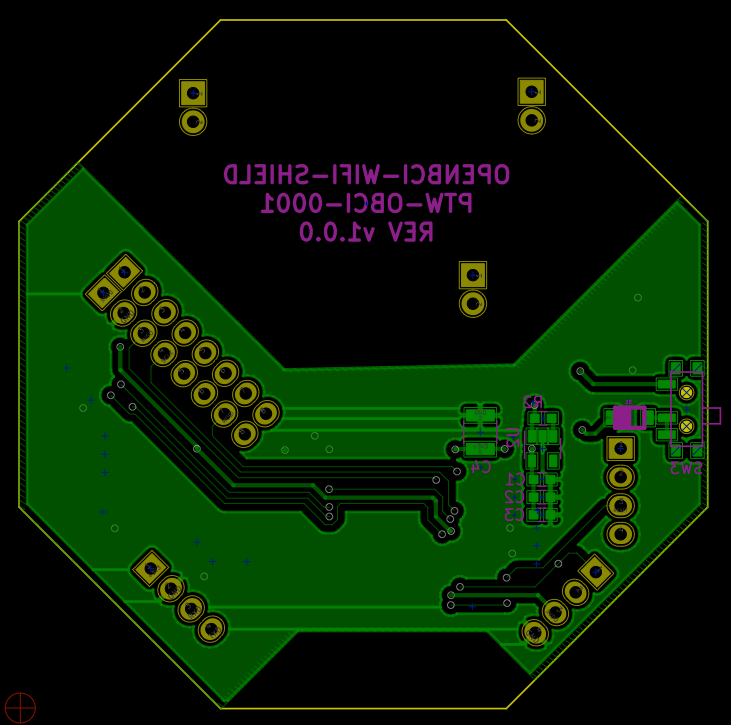
Wifi Board PCB Layer Images
Top Layer
Bottom Layer
Buttons
The top push button, RESET, is a reset button that will power cycle the ESP8266 chip. Don't press the RESET button when a Ganglion is attached, if you want to power cycle the WiFi Shield, send a ; command to the Ganglion or Cyton to trigger a power on reset of the WiFi Shield. The bottom button, PROG, is use for programming the WiFi Shield over serial UART and is hooked up to GPIO 0.
GPIO Pins Used by WiFi Shield
The WiFi Shield breaks out every GPIO on the Cyton and Ganglion, however, two of the GIPO pins have been used to make the WiFi Shield work, one pin is used for reset and the other is for a chip select line used in SPI communications.
Cyton
The WiFi Shield uses D13 and D18, leaving three other pins, D11, D12, and D17. In analog mode this means you can't read A7 when WiFi Shield is attached.
Ganglion
The WiFi Shield uses D_24 and D_4 (A_5). Leaving all other pints open for use!